L07 · Interrupts & P6
Topic: out-of-order · 55 pages
EECS 4340 — Lecture 7: Precise Interrupts & P6 Microarchitecture
Show slide text
EECS 4340
Lecture 7
Precise Interrupts & P6 Microarchitecture
Spring 2026
Prof. Tanvir Ahmed Khan
Slides developed in part by Profs. Austin, Brehob, Falsafi, Hill, Hoe, Lipasti, Martin, Roth, Shen, Smith, Sohi, Tyson, Vijaykumar, and Wenisch of Carnegie Mellon University, Purdue University, University of Michigan, University of Pennsylvania, and University of Wisconsin.
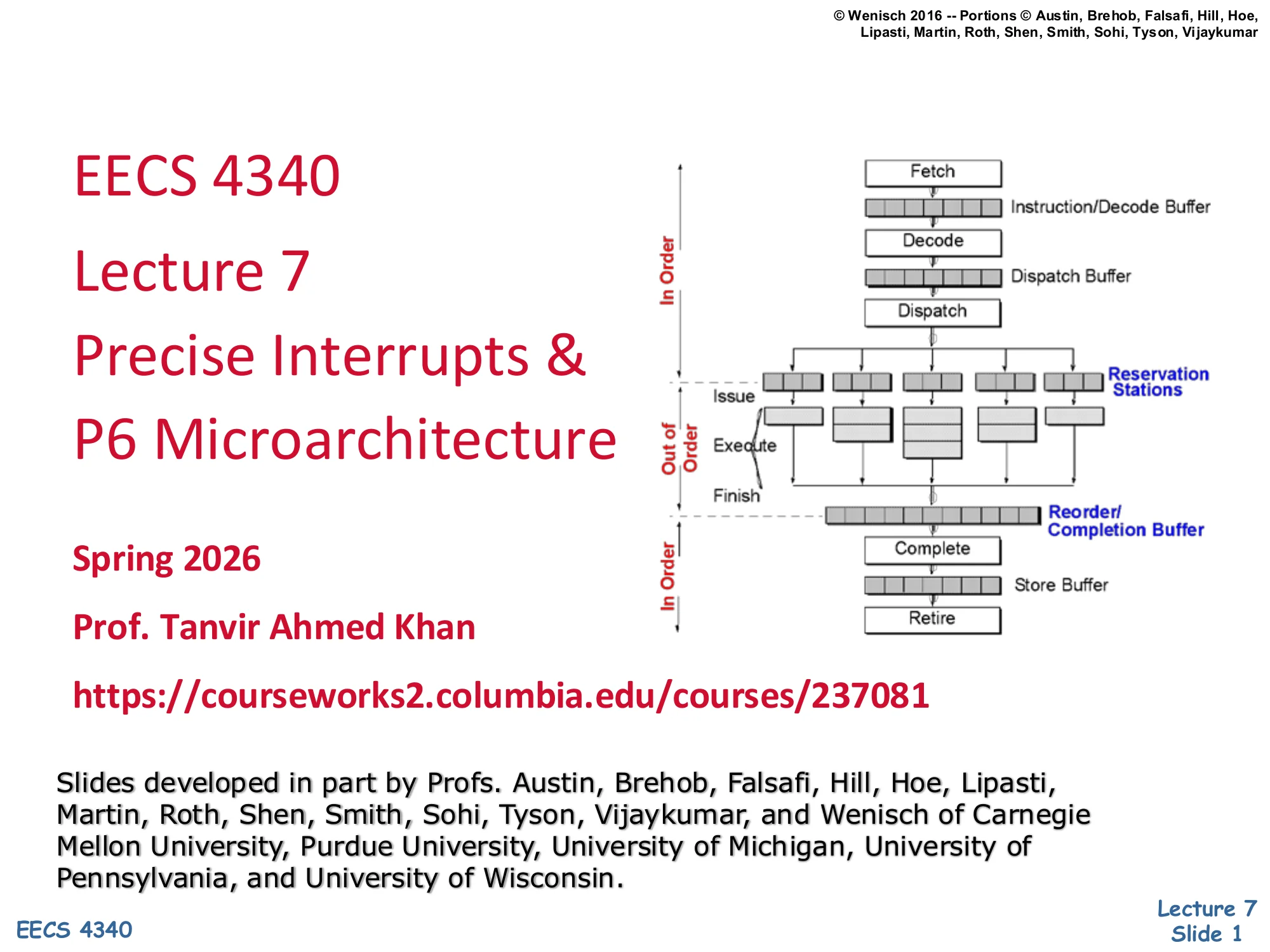
Right side: P6-style pipeline diagram with In-Order fetch/decode/dispatch, Out-of-Order issue/execute/finish through reservation stations, and In-Order completion/retire through a reorder/completion buffer plus store buffer.
Title slide for Lecture 7 of EECS 4340. The lecture extends Tomasulo’s algorithm with a reorder buffer so the machine can implement precise interrupts and recover cleanly from speculative mispredictions. The miniature pipeline picture on the right previews the answer that the rest of the lecture builds: instructions are fetched, decoded, and dispatched in program order; they then issue, execute, and finish out of order through a sea of reservation stations; results travel through a reorder/completion buffer and a store buffer that retire in program order. That two-phase structure — out-of-order body, in-order ends — is the defining shape of the P6 microarchitecture (Pentium Pro and its descendants).
Announcements
Show slide text
Announcements
- Project #4
- Due: proposal, 4-Mar-26
- Mid-term exam
- 9-Mar-26
Course logistics: the Project #4 proposal is due 4-Mar-26 and the mid-term exam is 9-Mar-26. The CourseWorks link points to the section landing page. No technical content on this slide.
Readings

Show slide text
Readings
For today:
- H & P Chapter 3.8–3.9, C.4–C.5
- Implementing precise interrupts in pipelined processors, https://ieeexplore.ieee.org/abstract/document/4607
- H & P Chapter 3.13
For next Wednesday:
- The MIPS R10000 Superscalar Microprocessor, https://ieeexplore.ieee.org/abstract/document/491460
Reading list for the lecture. The Hennessy & Patterson sections cover hardware-based speculation and the case study chapters; the Smith & Pleszkun Implementing precise interrupts paper is the foundational paper for precise interrupts and the reorder buffer idea, which the P6 design uses directly. The next reading on the MIPS R10000 sets up the contrast with explicit physical register renaming discussed in the next lecture.
Recap: Tomasulo's Algorithm
Show slide text
Recap: Tomasulo’s Algorithm
Section header. The next several slides recap Tomasulo’s algorithm before extending it with a ROB to support precise interrupts.
Tomasulo Data Structures
Show slide text
Tomasulo Data Structures
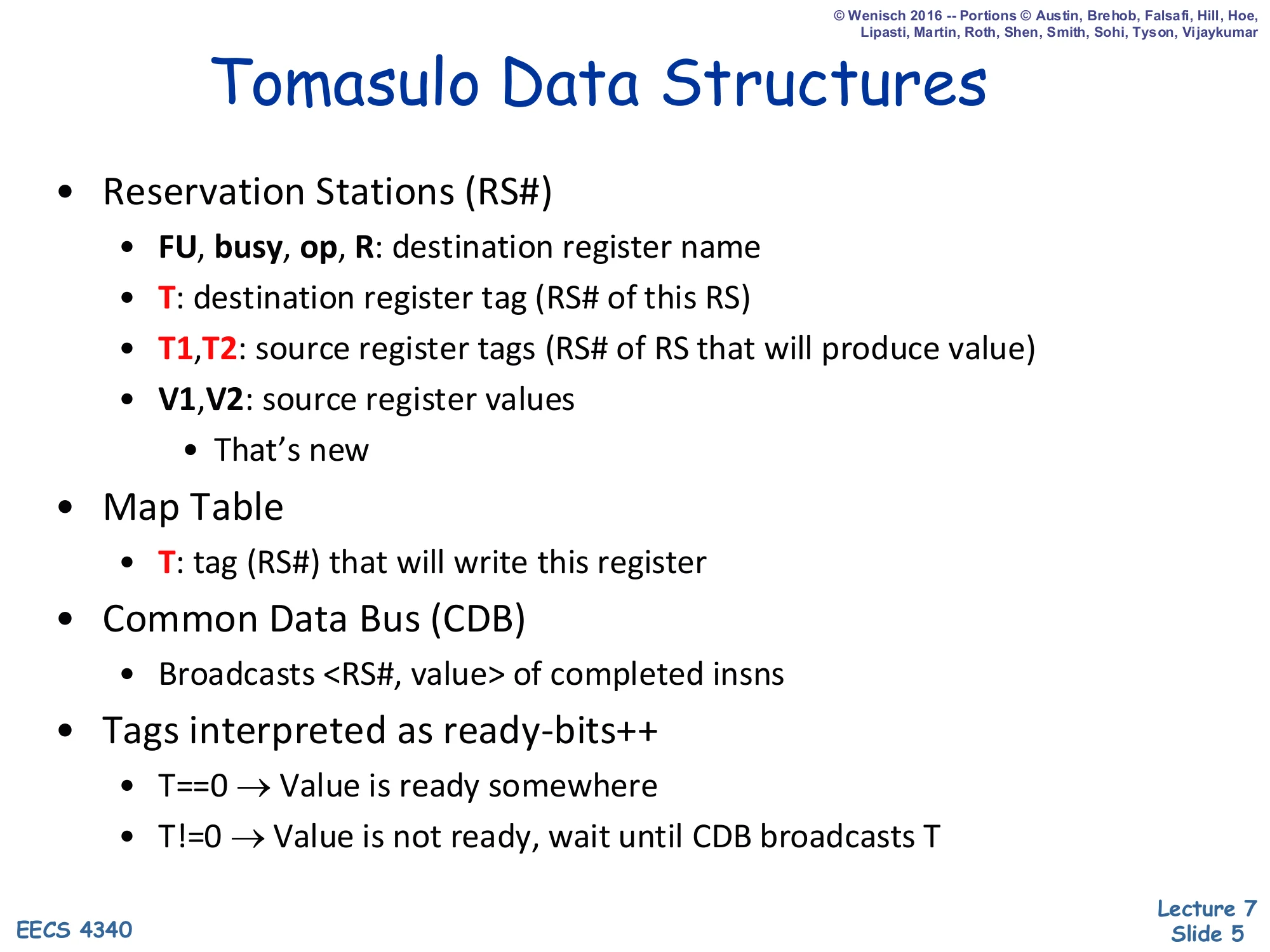
- Reservation Stations (RS#)
- FU, busy, op, R: destination register name
- T: destination register tag (RS# of this RS)
- T1, T2: source register tags (RS# of RS that will produce value)
- V1, V2: source register values
- That’s new
- Map Table
- T: tag (RS#) that will write this register
- Common Data Bus (CDB)
- Broadcasts
<RS#, value>of completed insns
- Broadcasts
- Tags interpreted as ready-bits++
- T==0→ Value is ready somewhere
- T=0→ Value is not ready, wait until CDB broadcasts T
Recap of Tomasulo’s core state. Each reservation station is identified by an RS# tag that names where the result will appear; the same tag is used by consumers as T1 or T2 until the CDB broadcasts a <RS#, value> pair, at which point the consumer latches the value into V1/V2. The Map Table is the renaming layer: it maps each architectural register to the RS# of the latest in-flight producer. The convention T==0 means ready (use the regfile copy), and T!=0 means waiting (snoop the CDB for that tag). This tag-as-ready-bit interpretation is what lets the machine resolve RAW hazards dynamically without ever stalling on WAR or WAW dependences.
Simple Tomasulo Data Structures
Show slide text
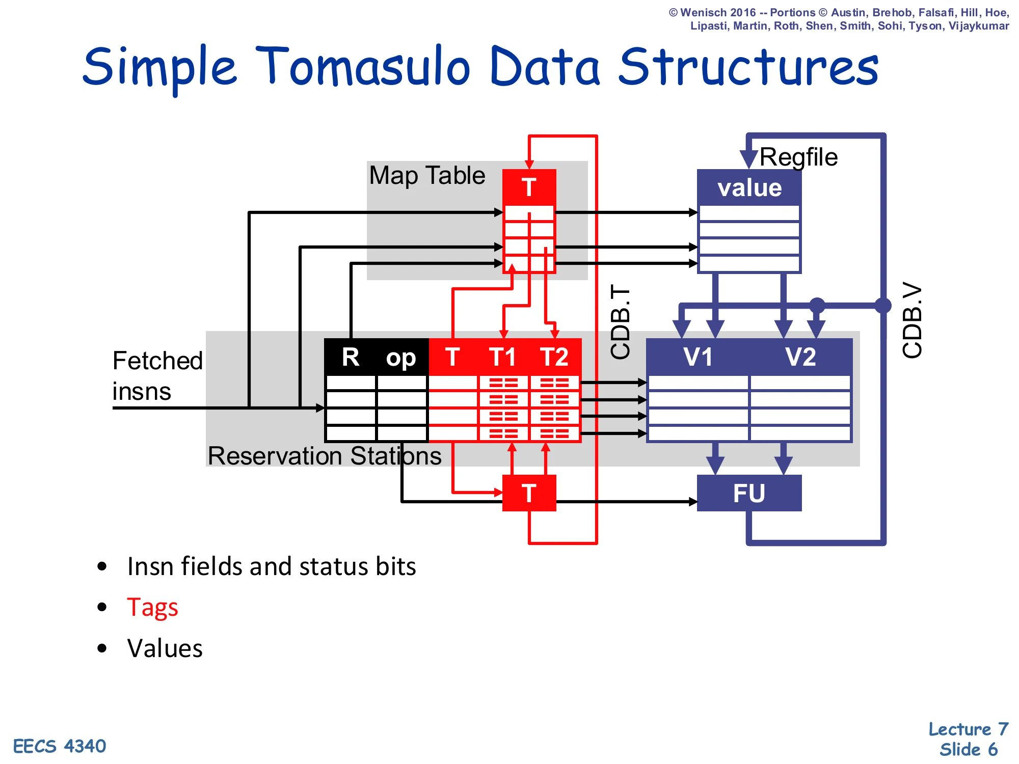
Simple Tomasulo Data Structures
Diagram showing the Map Table (column T) feeding tags into the Reservation Stations table (columns R, op, T, T1, T2) and the parallel Regfile (column value) feeding values into the RS value columns V1, V2. The output T tag of each RS feeds back into the Map Table. The CDB carries two wires labelled CDB.T and CDB.V that broadcast back to all RS slots and to the regfile. A functional unit (FU) consumes V1, V2 from the issuing RS and produces values that go onto the CDB.
- Insn fields and status bits
- Tags
- Values
Picture form of the previous slide. Tag plumbing is highlighted in red, value plumbing in blue. When a fetched instruction enters an RS, its destination tag is written into the Map Table for the architectural destination; its source tags are looked up by reading that table. A tag of 0 means the regfile copy is current and the value is read directly into V1/V2. A nonzero tag means the slot waits, watching the CDB for a matching CDB.T. When a reservation station fires, it consumes V1/V2, runs the FU, and broadcasts <CDB.T, CDB.V> to every other RS and the regfile so that everyone updates atomically.
Simple Tomasulo Pipeline
Show slide text
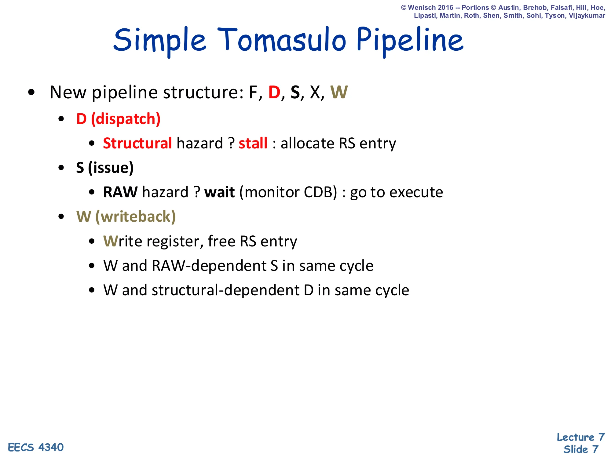
Simple Tomasulo Pipeline
- New pipeline structure: F, D, S, X, W
- D (dispatch)
- Structural hazard ? stall : allocate RS entry
- S (issue)
- RAW hazard ? wait (monitor CDB) : go to execute
- W (writeback)
- Write register, free RS entry
- W and RAW-dependent S in same cycle
- W and structural-dependent D in same cycle
- D (dispatch)
The Tomasulo pipeline splits classic decode into two stages: in-order Dispatch, which allocates a reservation station (stall on a structural hazard when no RS is free), and out-of-order isSue, which lets an instruction leave the RS once both source operands are available — a RAW hazard manifests here as a wait, not a stall, because dispatch keeps feeding younger instructions past the waiting one. Writeback (W) both writes the register file and forwards on the CDB to dependent RS slots; the two annotations W and RAW-dependent S in same cycle and W and structural-dependent D in same cycle are the standard pipelining forwards that keep this loop tight.
Value/Copy-Based Register Renaming
Show slide text
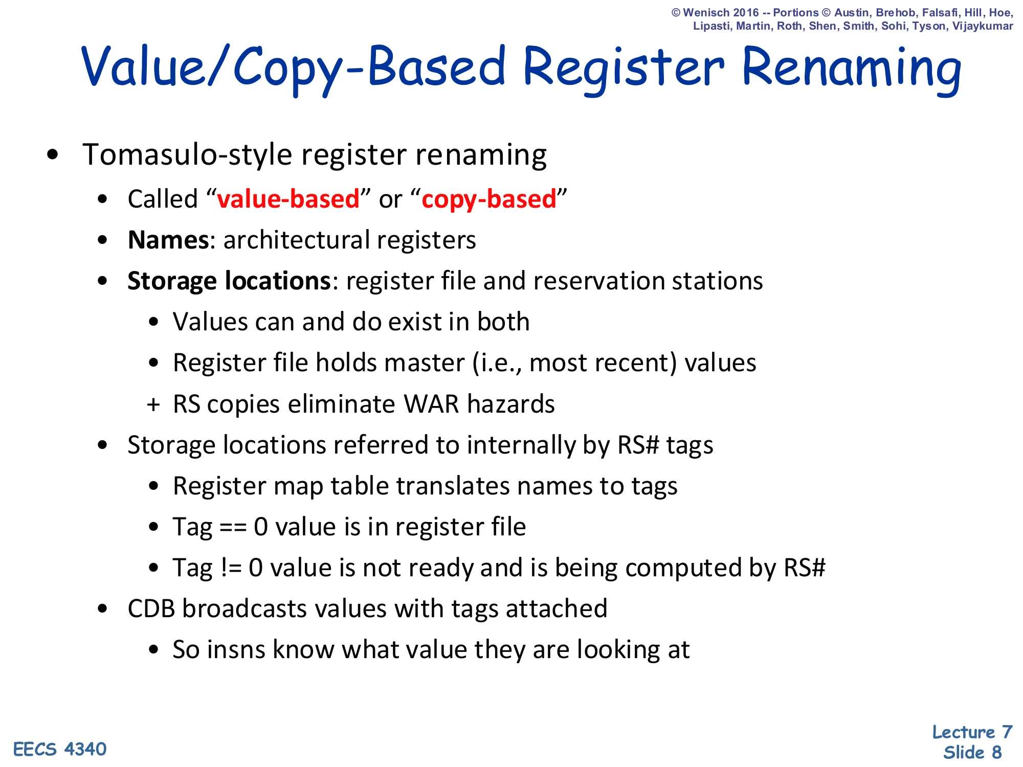
Value/Copy-Based Register Renaming
- Tomasulo-style register renaming
- Called “value-based” or “copy-based”
- Names: architectural registers
- Storage locations: register file and reservation stations
- Values can and do exist in both
- Register file holds master (i.e., most recent) values
-
- RS copies eliminate WAR hazards
- Storage locations referred to internally by RS# tags
- Register map table translates names to tags
- Tag == 0 value is in register file
- Tag != 0 value is not ready and is being computed by RS#
- CDB broadcasts values with tags attached
- So insns know what value they are looking at
Tomasulo’s flavor of renaming is value-based: the values live in the register file and in any reservation station that grabbed a copy of them, while the names that consumers use are RS# tags rather than architectural register numbers. Because each RS keeps its own snapshot of the source operands, WAR hazards disappear — a later writer cannot overwrite the older reader’s copy because the old reader already has its private value. This is the contrast with the physical-register-file style introduced later (R10000): there, only one storage location per dynamic value exists. The CDB always broadcasts <tag, value> so every waiting consumer can decide whether the broadcast is the producer it is waiting for.
Dynamic Scheduling Summary
Show slide text
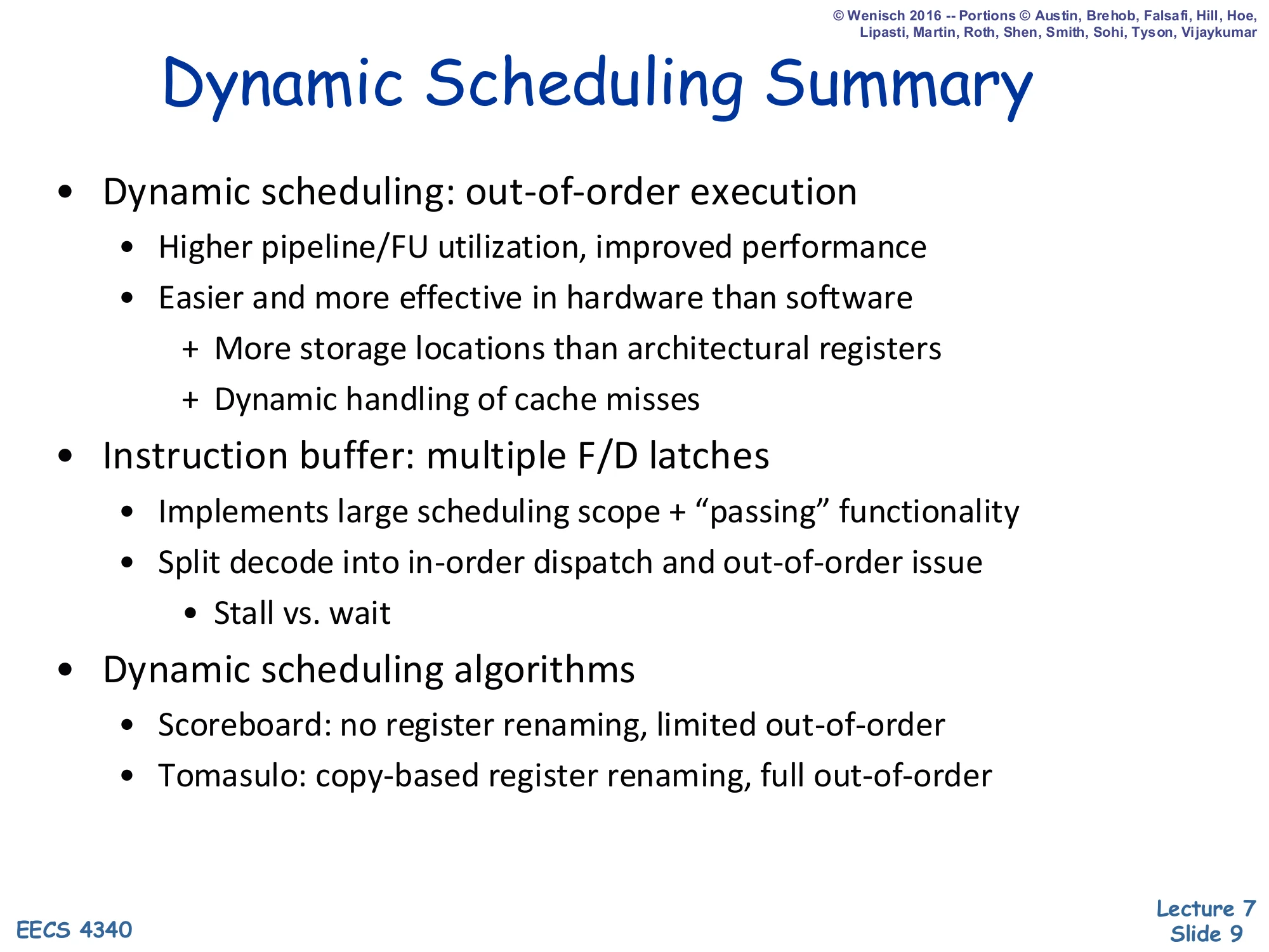
Dynamic Scheduling Summary
- Dynamic scheduling: out-of-order execution
- Higher pipeline/FU utilization, improved performance
- Easier and more effective in hardware than software
-
- More storage locations than architectural registers
-
- Dynamic handling of cache misses
-
- Instruction buffer: multiple F/D latches
- Implements large scheduling scope + “passing” functionality
- Split decode into in-order dispatch and out-of-order issue
- Stall vs. wait
- Dynamic scheduling algorithms
- Scoreboard: no register renaming, limited out-of-order
- Tomasulo: copy-based register renaming, full out-of-order
Capstone summary of the dynamic-scheduling thread so far. The key engineering insight is the instruction buffer (a reservation station pool or scoreboard): by giving instructions a place to sit between in-order dispatch and out-of-order issue, the hardware turns stalls (front-end-blocking) into waits (only the affected instruction stops). Hardware has two structural advantages over a static (compiler) schedule: it has more storage locations than the ISA exposes, and it can react to dynamic events such as cache misses. The two algorithms compared on this slide differ exactly in how aggressively they use those extra storage slots — scoreboarding keeps architectural names (no renaming), while Tomasulo uses RS-resident copies as renamed storage.
Are we done?
Show slide text
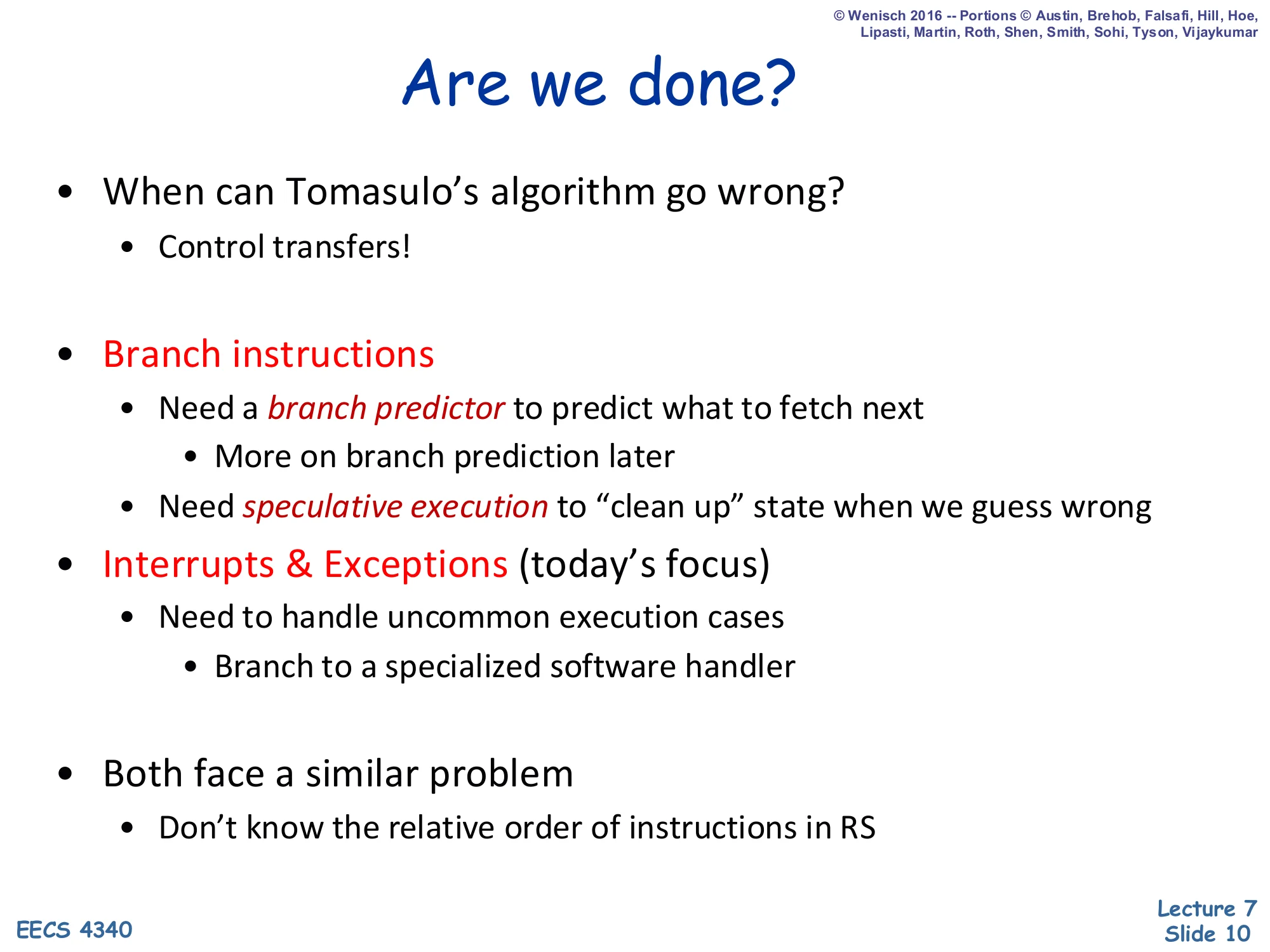
Are we done?
- When can Tomasulo’s algorithm go wrong?
- Control transfers!
- Branch instructions
- Need a branch predictor to predict what to fetch next
- More on branch prediction later
- Need speculative execution to “clean up” state when we guess wrong
- Need a branch predictor to predict what to fetch next
- Interrupts & Exceptions (today’s focus)
- Need to handle uncommon execution cases
- Branch to a specialized software handler
- Need to handle uncommon execution cases
- Both face a similar problem
- Don’t know the relative order of instructions in RS
This slide is the bridge from Tomasulo to today’s topic. Plain Tomasulo handles data hazards beautifully, but it has no story for control events: a mispredicted branch (recovered via speculative execution) and a precise interrupt or exception both require the hardware to identify a sharp program-order boundary and undo everything younger than it. Because instructions sit in RS slots out of program order, the machine literally cannot tell which instruction is older than the offending one without an additional structure. That structure — the reorder buffer — is what the rest of the lecture introduces.
Interrupts
Show slide text
Interrupts
Section header. The next several slides define interrupts precisely (synchronous vs. asynchronous, restartable, transparent) before motivating the ROB.
Interrupts
Show slide text
Interrupts
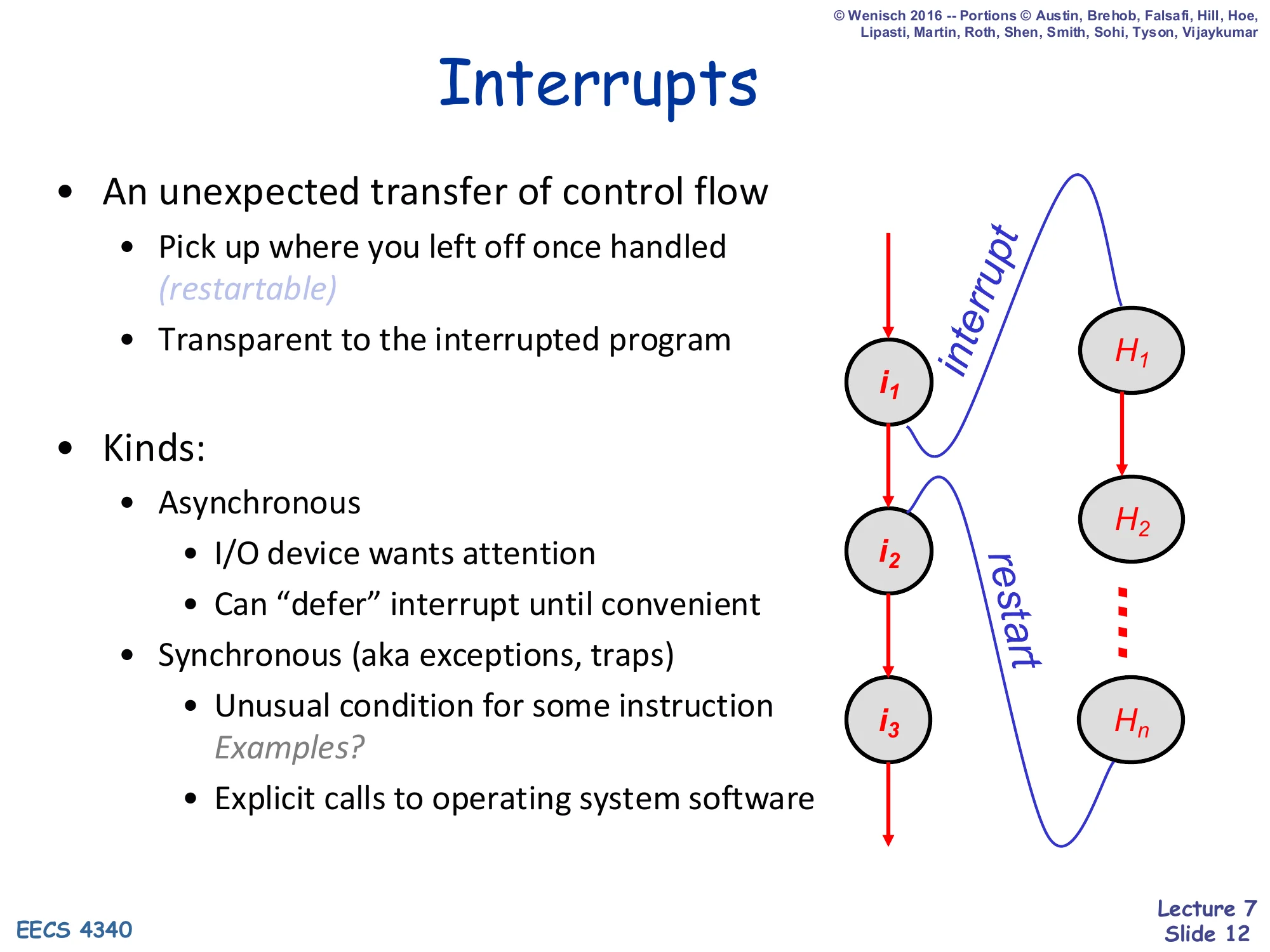
- An unexpected transfer of control flow
- Pick up where you left off once handled (restartable)
- Transparent to the interrupted program
- Kinds:
- Asynchronous
- I/O device wants attention
- Can “defer” interrupt until convenient
- Synchronous (aka exceptions, traps)
- Unusual condition for some instruction Examples?
- Explicit calls to operating system software
- Asynchronous
Right side: timeline showing user-program instructions i1,i2,i3 being preempted by a handler with instructions H1,H2,…,Hn, then control returning (“restart”) to the spot in the user program where the interrupt fired.
An interrupt is an unexpected transfer of control: the program does not call the handler, the hardware redirects to it, and the architecture must hide this fact so the user program is none the wiser when it resumes. Two kinds matter. Asynchronous interrupts come from outside the pipeline (timer, device) and the hardware has scheduling freedom — it can wait for a convenient retirement boundary. Synchronous interrupts (exceptions, traps, faults, system calls) are caused by an instruction — page faults, divide-by-zero, illegal opcodes, syscalls — and the architecture has no freedom: the handler must see exactly the state that would exist if every instruction up to and including (or up to but not including) the offender had finished. That semantic constraint is what motivates precise interrupts and the ROB.
Precise Interrupts
Show slide text
Precise Interrupts
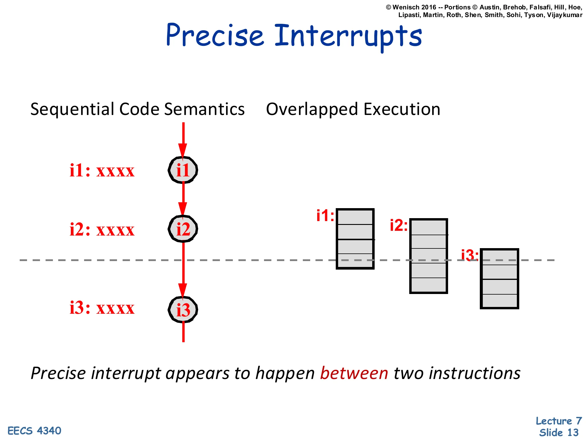
Left: Sequential Code Semantics — instructions i1, i2, i3 execute in strict program order, and the dashed line shows a clean cut between i2 and i3.
Right: Overlapped Execution — i1, i2, i3 run as overlapped pipeline boxes, but the same dashed line still slices through them — i1 has fully retired, i2 is partway done, i3 has barely started.
Precise interrupt appears to happen between two instructions.
The picture nails the contract. Sequentially, an interrupt happens between two instructions: everything before the cut is committed; everything after is as if it never started. Pipelined or out-of-order, instructions overlap, so at the moment the interrupt is recognised, parts of younger instructions are already in-flight — the dashed line cuts straight through their pipeline boxes. To honor the sequential semantics, the hardware must roll back the partial effects of any in-flight instruction younger than the cut and complete every instruction older than the cut. That roll-forward / roll-back capability is what makes an interrupt precise.
Speculation and Precise Interrupts
Show slide text
Speculation and Precise Interrupts
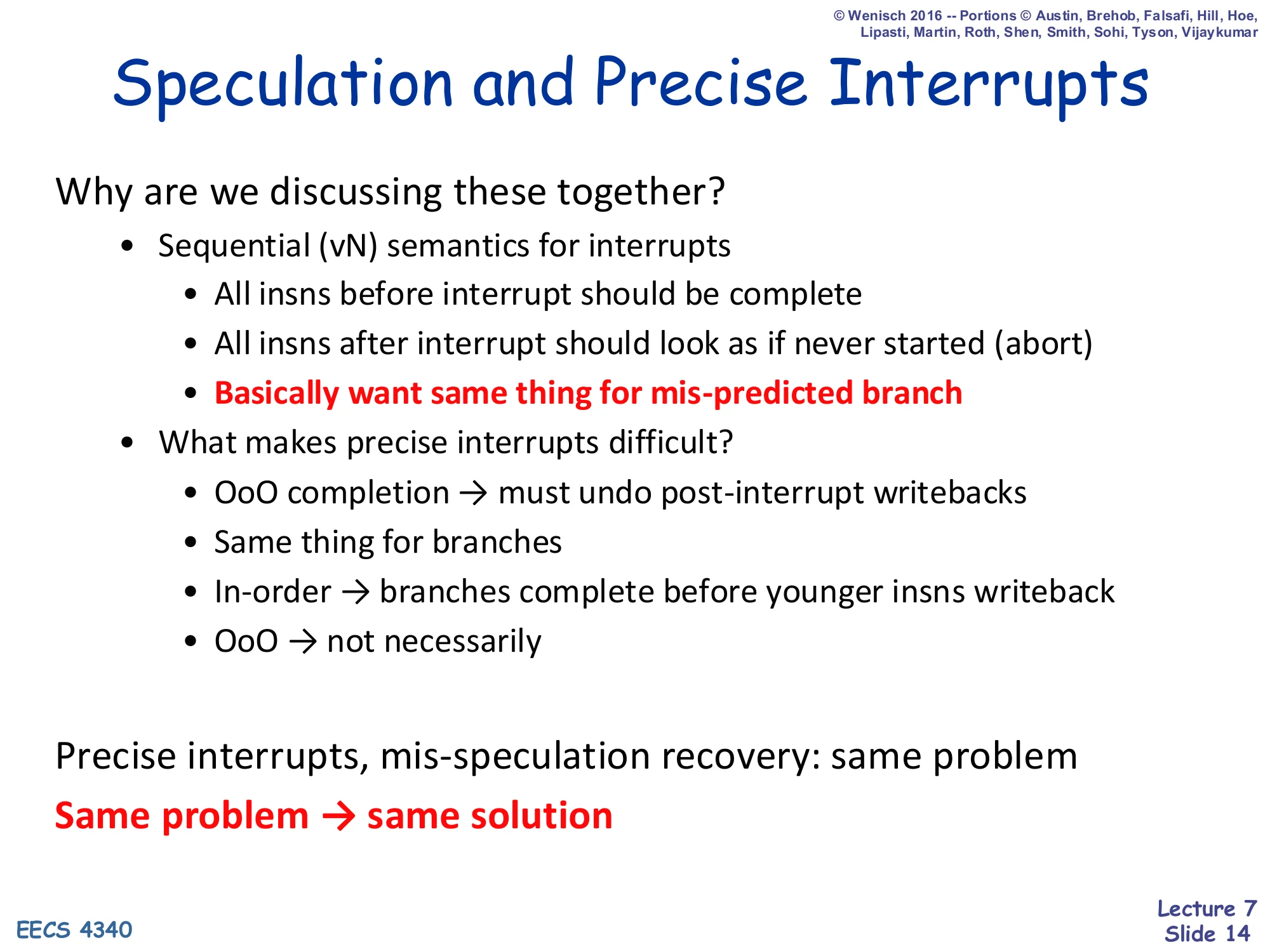
Why are we discussing these together?
- Sequential (vN) semantics for interrupts
- All insns before interrupt should be complete
- All insns after interrupt should look as if never started (abort)
- Basically want same thing for mis-predicted branch
- What makes precise interrupts difficult?
- OoO completion → must undo post-interrupt writebacks
- Same thing for branches
- In-order → branches complete before younger insns writeback
- OoO → not necessarily
Precise interrupts, mis-speculation recovery: same problem
Same problem → same solution
The slide makes the central observation that motivates the entire lecture: a precise interrupt and speculative-misprediction recovery are the same problem. Both ask the hardware to commit everything older than a cut and abort everything younger. In an in-order pipeline this is automatic — younger instructions cannot have writebacks because they are physically behind the older ones — but in an out-of-order machine younger instructions may have already broadcast on the CDB and even written the register file. The whole rest of the lecture follows from this insight: build one mechanism, the ROB, that solves both.
Precise State
Show slide text
Precise State
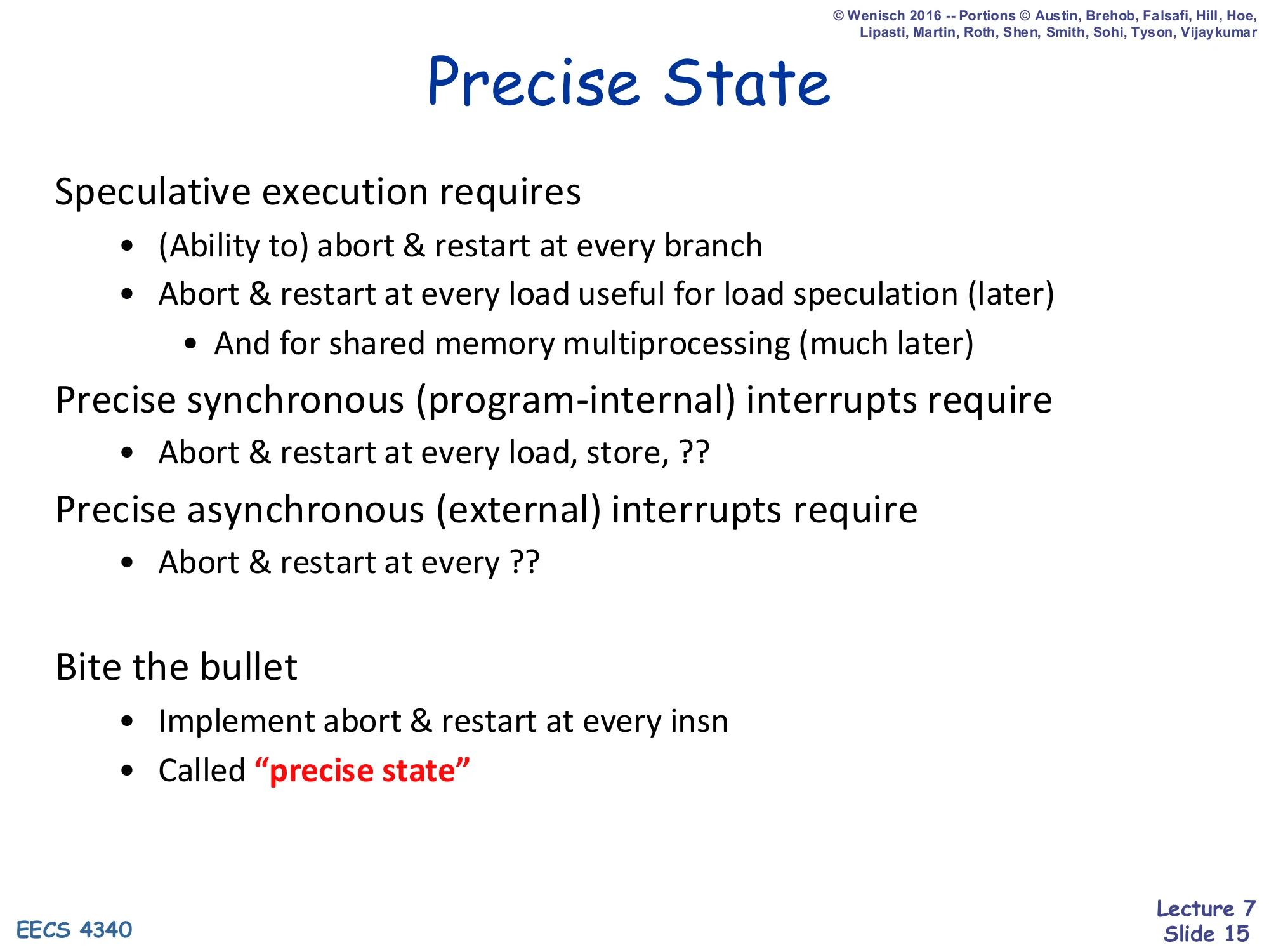
Speculative execution requires
- (Ability to) abort & restart at every branch
- Abort & restart at every load useful for load speculation (later)
- And for shared memory multiprocessing (much later)
Precise synchronous (program-internal) interrupts require
- Abort & restart at every load, store, ??
Precise asynchronous (external) interrupts require
- Abort & restart at every ??
Bite the bullet
- Implement abort & restart at every insn
- Called “precise state”
If you tried to design abort/restart only for the instructions that can fault, you would end up with a moving target: branches need it, loads/stores need it for exceptions like page faults, asynchronous interrupts can fire anywhere, and speculation adds load-speculation rollback on top. The slide’s recommendation — bite the bullet, implement abort & restart at every instruction — leads to the unified abstraction called precise state: at every instruction boundary the architectural state is as-if-sequential, so you can take an interrupt or recover from a branch misprediction at any boundary. This is exactly what the ROB delivers.
Precise State Options
Show slide text
Precise State Options
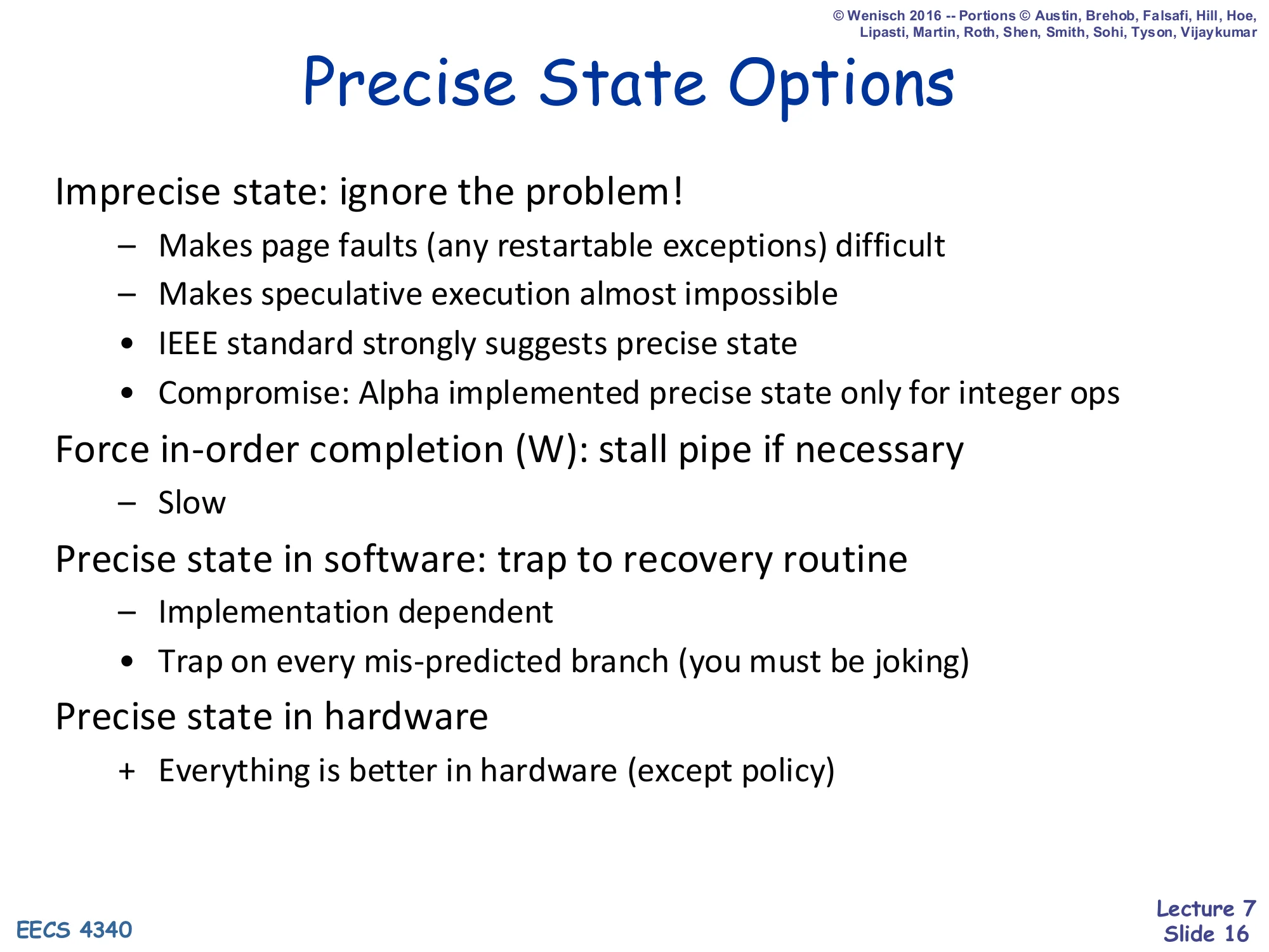
Imprecise state: ignore the problem!
- − Makes page faults (any restartable exceptions) difficult
- − Makes speculative execution almost impossible
- IEEE standard strongly suggests precise state
- Compromise: Alpha implemented precise state only for integer ops
Force in-order completion (W): stall pipe if necessary
- − Slow
Precise state in software: trap to recovery routine
- − Implementation dependent
- Trap on every mis-predicted branch (you must be joking)
Precise state in hardware
-
- Everything is better in hardware (except policy)
The slide enumerates the design space and explains why every alternative loses. Imprecise state makes page faults (which must be restartable) a nightmare and effectively rules out speculation. Force in-order completion preserves precise state by serializing writeback — which throws away all the out-of-order performance you fought to gain. Software precise state (trap-and-fix) requires a trap on every mispredicted branch, which is absurd. The remaining option, precise state in hardware, is the reorder buffer strategy, and the rest of the lecture builds it.
The Problem with Precise State
Show slide text
The Problem with Precise State
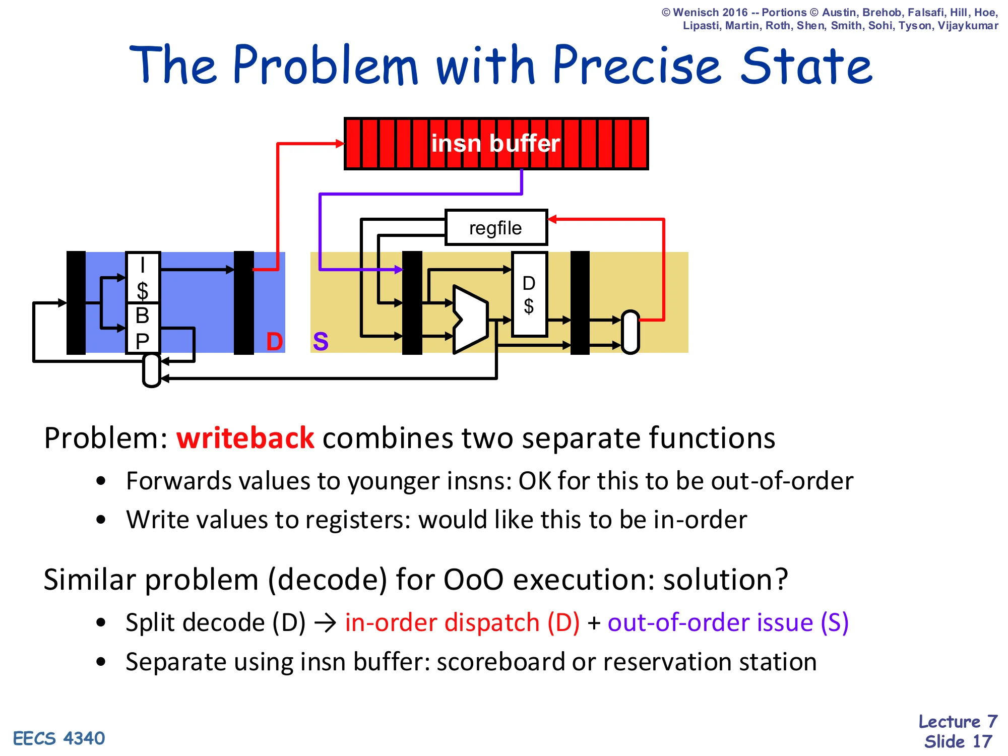
Diagram: a pipeline showing F (with I-cache and BP), an insn buffer between fetch and the back end, then the back end with regfile, ALU, D-cache, and a writeback latch. The D (dispatch) stage and S (issue) stage are highlighted in red and purple respectively in front of the insn buffer.
Problem: writeback combines two separate functions
- Forwards values to younger insns: OK for this to be out-of-order
- Write values to registers: would like this to be in-order
Similar problem (decode) for OoO execution: solution?
- Split decode (D) → in-order dispatch (D) + out-of-order issue (S)
- Separate using insn buffer: scoreboard or reservation station
The slide diagnoses the problem precisely. Writeback in a classic pipeline is overloaded: it forwards a result to dependent younger instructions (which we want to do as soon as possible, out of order, for performance) and it commits the result to the architectural register file (which we want to do in program order for precise state). The fix is the same trick used to split decode into in-order dispatch and out-of-order issue: split writeback so forwarding stays out-of-order while commit becomes in-order, separated by another buffer — the ROB.
Re-Order Buffer (ROB)
Show slide text
Re-Order Buffer (ROB)
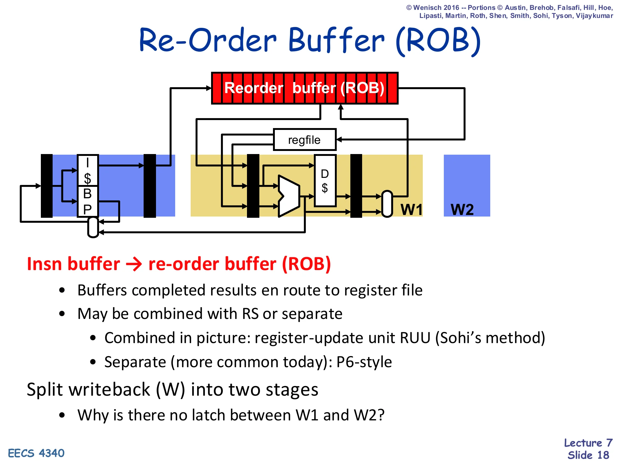
Diagram: fetch + I-cache + BP feeding the same back-end as before, but now a Reorder buffer (ROB) sits above the regfile. Two writeback latches W1 and W2 are shown — but no latch between them.
Insn buffer → re-order buffer (ROB)
- Buffers completed results en route to register file
- May be combined with RS or separate
- Combined in picture: register-update unit RUU (Sohi’s method)
- Separate (more common today): P6-style
Split writeback (W) into two stages
- Why is there no latch between W1 and W2?
The reorder buffer is just a FIFO of in-flight instructions tagged in dispatch order. Completed values flow into the ROB en route to the regfile but do not commit until they reach the head in program order. Two flavors are mentioned: Sohi’s register update unit combines the ROB with the reservation stations in one structure, while the P6-style keeps them separate, which is more common and is what this lecture builds. The split-writeback question (no latch between W1 and W2) is a teaser — the answer is on the next slide: W1 (complete) writes into the ROB, while W2 (retire) writes into the regfile, and the ROB itself is the storage that replaces the latch.
Complete and Retire
Show slide text
Complete and Retire
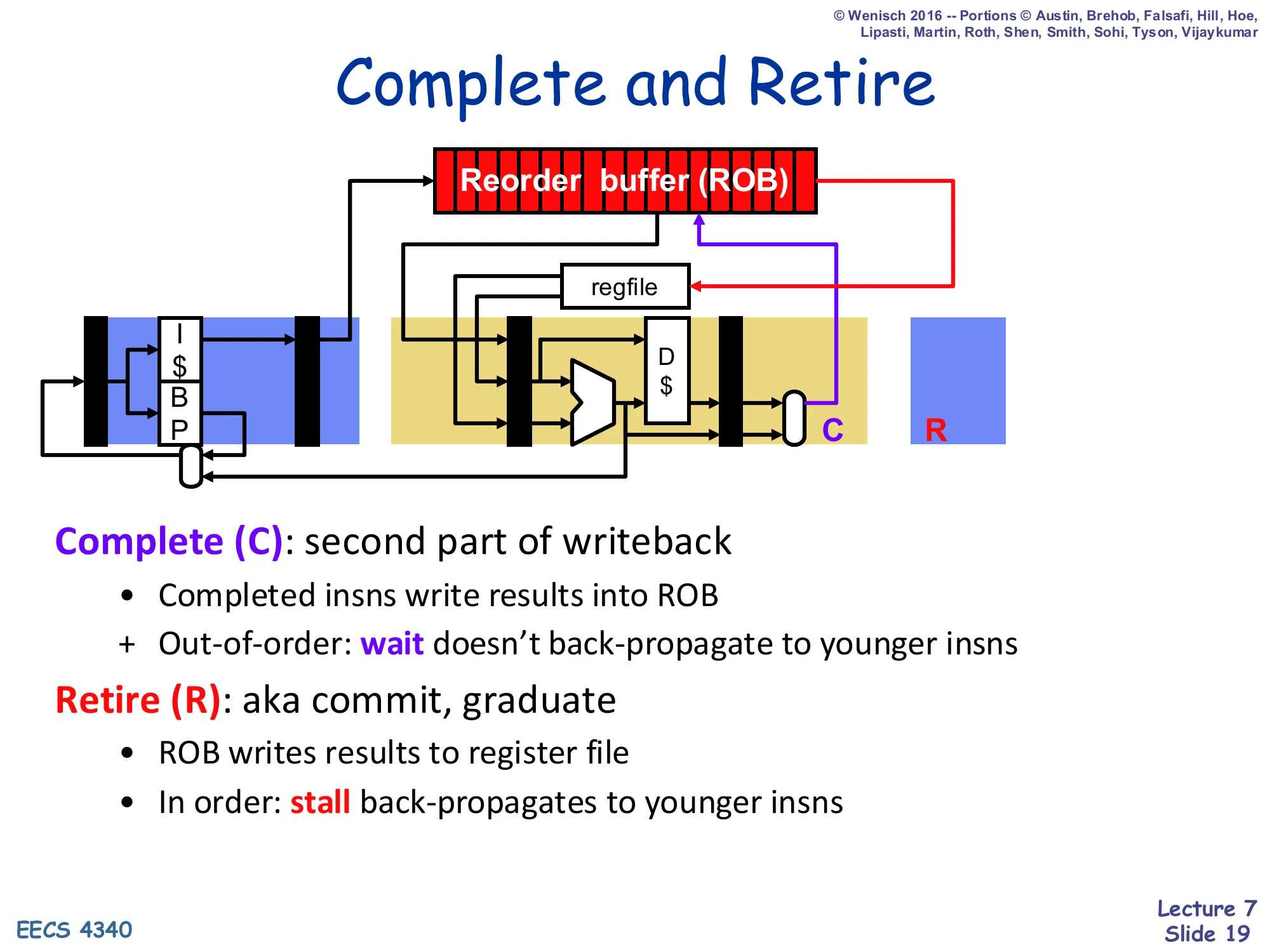
Same back-end picture, with stages now labelled C (complete, purple) and R (retire, red).
Complete (C): second part of writeback
- Completed insns write results into ROB
-
- Out-of-order: wait doesn’t back-propagate to younger insns
Retire (R): aka commit, graduate
- ROB writes results to register file
- In order: stall back-propagates to younger insns
The slide names the two new stages. Complete (C) is out-of-order: a finished functional unit writes its value into its ROB slot and broadcasts on the CDB to dependents. Because complete is OoO, a stall in C only delays that instruction — younger instructions can complete out from under it. Retire (R), also called commit or graduate, is strictly in-order: only the ROB head retires per cycle, writing its value to the regfile. Because retire is in-order, a stall in R does back-propagate — the head blocks the entire back of the queue. That asymmetry is exactly what gives the ROB its precise-state guarantee.
Load/Store Queue (LSQ)
Show slide text
Load/Store Queue (LSQ)
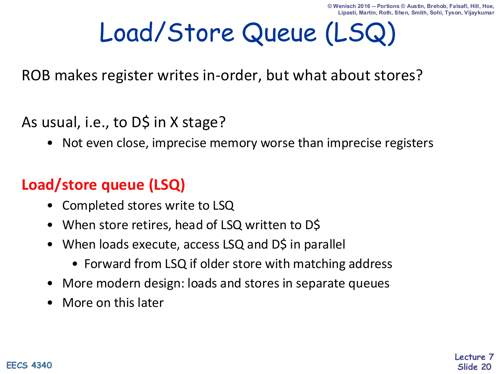
ROB makes register writes in-order, but what about stores?
As usual, i.e., to D$ in X stage?
- Not even close, imprecise memory worse than imprecise registers
Load/store queue (LSQ)
- Completed stores write to LSQ
- When store retires, head of LSQ written to D$
- When loads execute, access LSQ and D$ in parallel
- Forward from LSQ if older store with matching address
- More modern design: loads and stores in separate queues
Registers are not the only architectural state — memory is too. A precise register file plus an imprecise D-cache is no good: a faulting instruction must not have its store committed. The fix is symmetric to the ROB: a load/store queue holds completed-but-not-yet-retired stores. A store does not touch the cache until it retires from the LSQ head; meanwhile loads execute speculatively but disambiguate against the LSQ — a load with a matching address against an older in-flight store forwards the store’s pending value rather than reading stale data from the cache. This combination — ROB for registers, LSQ for memory — is what gives P6 its complete precise-state guarantee.
ROB + LSQ
Show slide text
ROB + LSQ
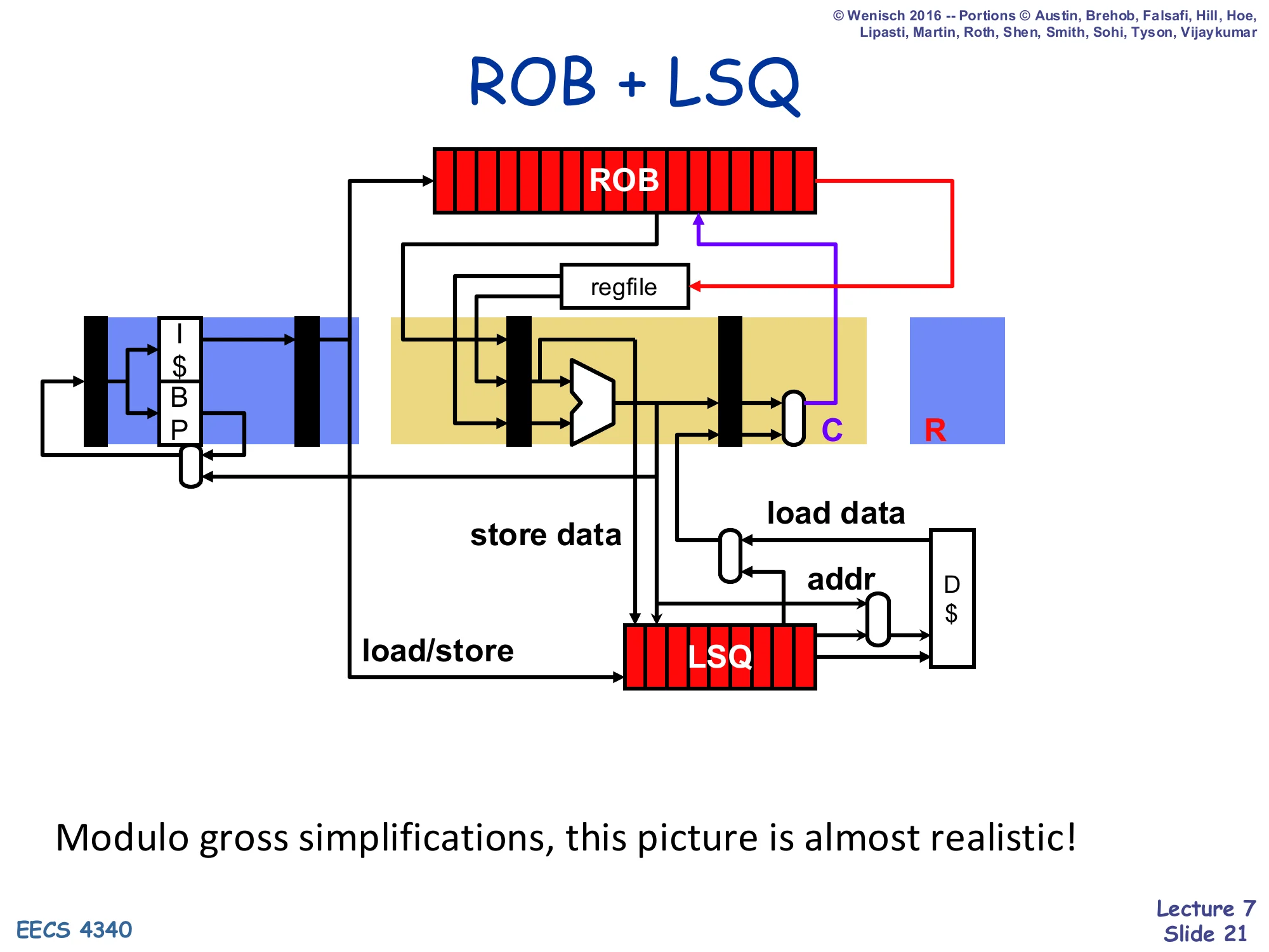
Full data-path picture: F + I-cache + BP feeds the dispatch latch. The ROB sits above the regfile and ALU. After the ALU, addresses and store-data feed into a separate LSQ that is also fed by load/store dispatch. The LSQ produces an addr going to the D-cache and consumes load data coming back. The complete (C) and retire (R) stages are explicit on the right.
Modulo gross simplifications, this picture is almost realistic!
Putting it all together: this is the canonical P6-style block diagram. Front-end stays in order (F + decode/dispatch). The middle is OoO: RSes feed the ALU and the LSQ in parallel. The back-end is in order again (C → R) via the ROB and the LSQ. Note in particular that the D-cache is downstream of the LSQ, not the ALU directly — that placement is exactly what makes memory state precise: the cache only sees stores that have already retired in program order.
P6 Microarchitecture

Show slide text
P6 Microarchitecture
Section header. The remaining slides specialise the generic ROB design into the concrete P6 microarchitecture (Pentium Pro / Pentium II / Pentium III), defining its data structures, pipeline stages, and walking a 12-cycle example.
P6
Show slide text
P6
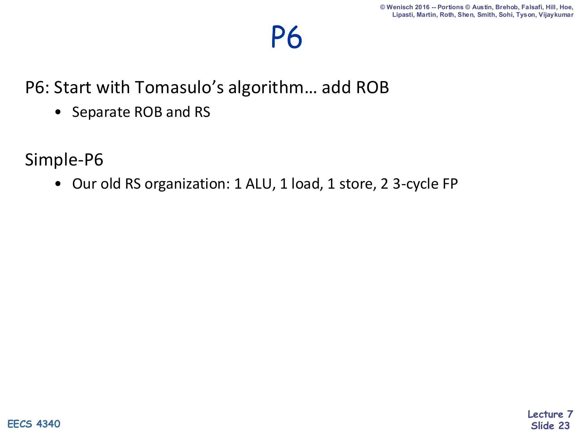
P6: Start with Tomasulo’s algorithm… add ROB
- Separate ROB and RS
Simple-P6
- Our old RS organization: 1 ALU, 1 load, 1 store, 2 3-cycle FP
P6 is exactly Tomasulo + a separate ROB. The reservation stations and the ROB live in different physical structures, which is the key contrast with Sohi’s RUU. To keep the example tractable, the lecture uses Simple-P6 with five reservation stations: one ALU, one load, one store, and two 3-cycle FP units. Real P6 had more, but the data structures and pipeline are identical.
P6 Data Structures (T+ semantics)
Show slide text
P6 Data Structures
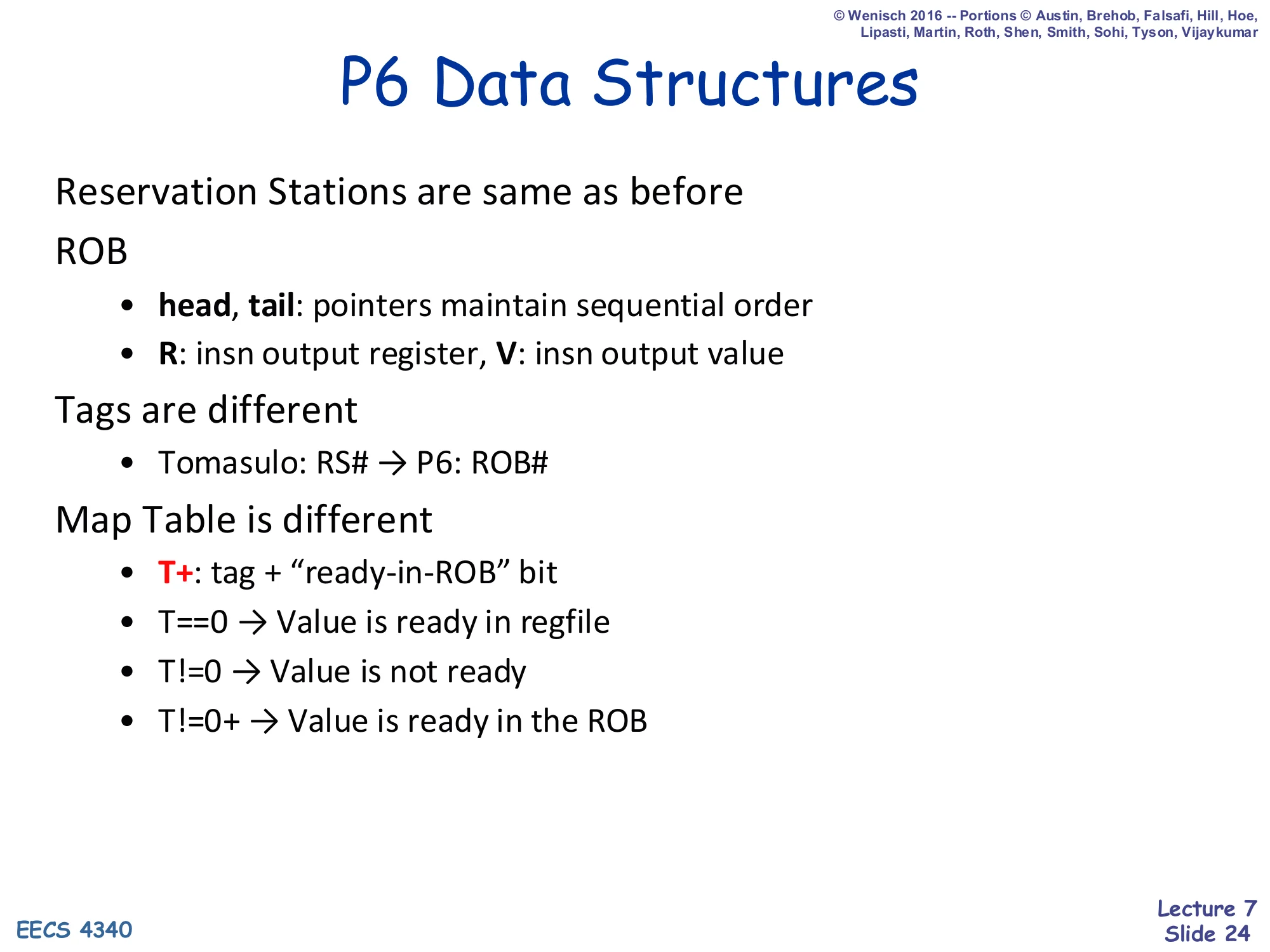
Reservation Stations are same as before
ROB
- head, tail: pointers maintain sequential order
- R: insn output register, V: insn output value
Tags are different
- Tomasulo: RS# → P6: ROB#
Map Table is different
- T+: tag + “ready-in-ROB” bit
- T==0→ Value is ready in regfile
- T=0→ Value is not ready
- T=0+→ Value is ready in the ROB
P6’s data structures evolve from Tomasulo’s in three ways. First, the reservation stations are unchanged in function but the tags they carry change: instead of RS# the tag is now the ROB#, the slot in the reorder buffer that the dispatching instruction was assigned. Tagging by ROB# is what gives every in-flight instruction a stable program-order identity. Second, the ROB itself stores R (architectural destination) and V (computed value) for each in-flight instruction, with head/tail pointers for in-order retirement. Third, the Map Table now stores T+ — a tag plus a ready-in-ROB bit. Three states result: T==0 (value lives in the regfile), T!=0 (value not computed yet), and T!=0+ (value computed but still in the ROB, not yet retired). The + bit is the crucial signal that lets dispatch read a finished-but-not-yet-retired result directly out of the ROB instead of waiting for retirement.
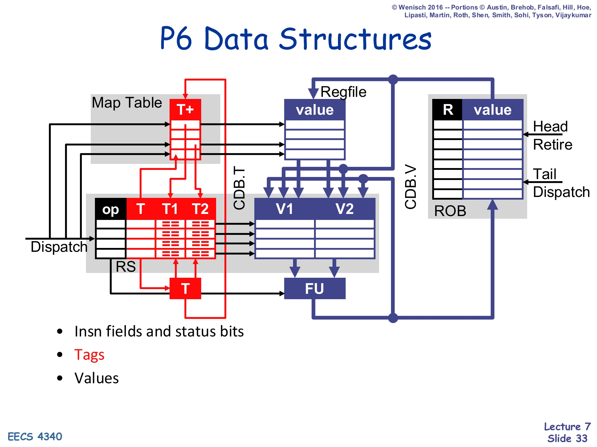
P6 Data Structures (diagram)

Show slide text
P6 Data Structures
Diagram: Map Table (column T+) sits between dispatch and the regfile. Reservation stations (columns op, T, T1, T2) feed FU through V1/V2 latches. CDB.T and CDB.V come back from the FU, into RS, into the regfile, and into the ROB (columns R, value) on the far right. The ROB has explicit Head/Retire and Tail/Dispatch pointers.
- Insn fields and status bits
- Tags
- Values
The picture form of the previous slide — the same Tomasulo diagram, but with a separate ROB FIFO grafted on the right and the Map Table column relabeled T+. Notice how data flows in P6: a result coming off the FU broadcasts on CDB.T/CDB.V; every RS slot, the regfile, and the ROB slot at index CDB.T are updated simultaneously. At retire, the ROB head writes its value into the regfile and frees its slot. The dispatch path on the left now has three sources for an operand: the regfile, the ROB (when T+), or a tag for later forwarding (when T only) — that three-way choice is what T+ encodes.
P6 Data Structures (worked-example template)
Show slide text
P6 Data Structures
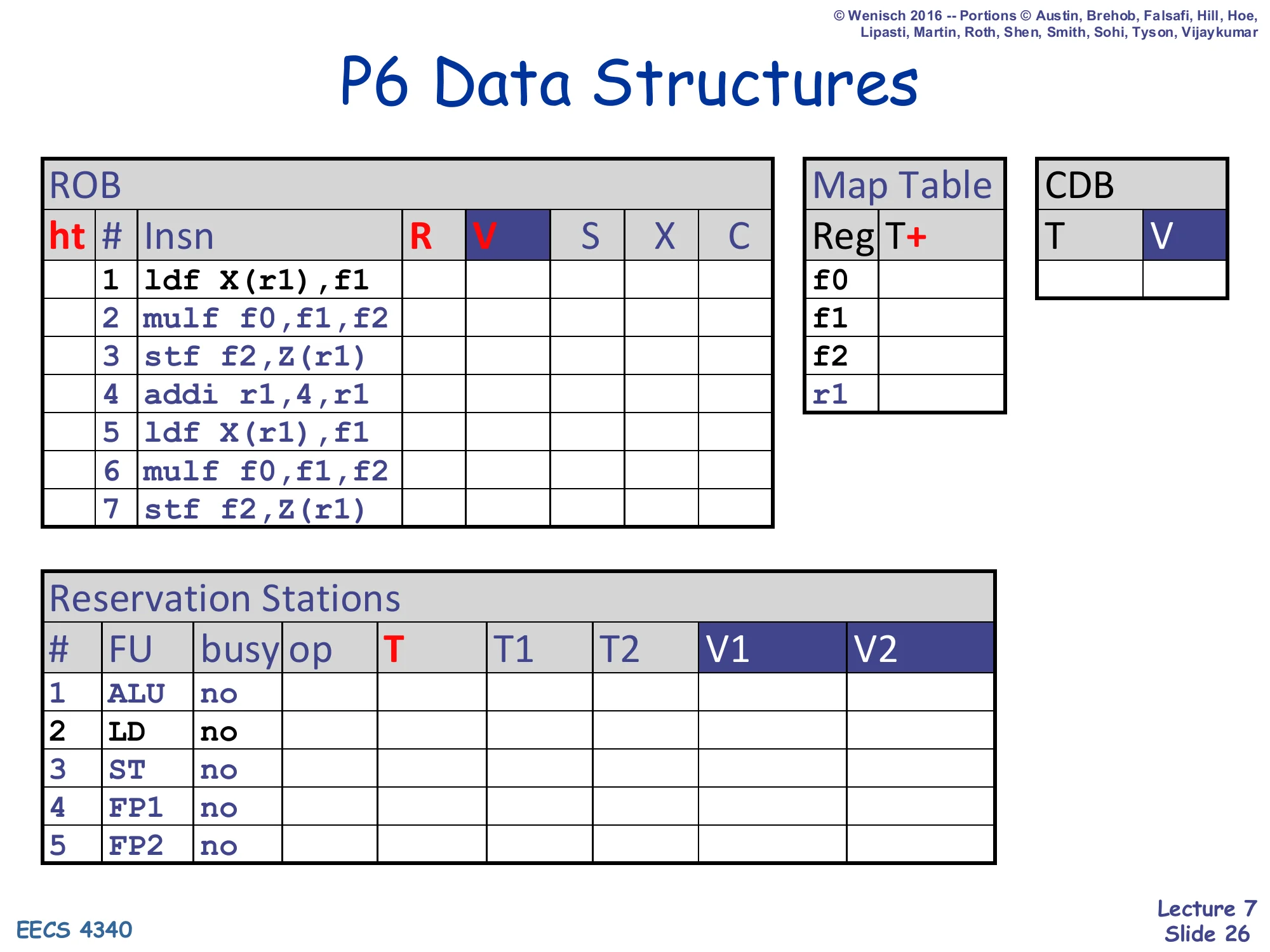
ROB columns: ht | # | Insn | R | V | S | X | C
ht # Insn R V S X C 1 ldf X(r1),f1 2 mulf f0,f1,f2 3 stf f2,Z(r1) 4 addi r1,4,r1 5 ldf X(r1),f1 6 mulf f0,f1,f2 7 stf f2,Z(r1)Map Table columns: Reg | T+ — entries f0, f1, f2, r1.
CDB columns: T | V.
Reservation Stations columns: # | FU | busy | op | T | T1 | T2 | V1 | V2.
| # | FU | busy |
|---|---|---|
| 1 | ALU | no |
| 2 | LD | no |
| 3 | ST | no |
| 4 | FP1 | no |
| 5 | FP2 | no |
Initial state of the worked example. Seven instructions form two iterations of a ldf / mulf / stf plus an induction-variable update addi r1,4,r1. The ROB has columns to record retire status (head/tail), the architectural destination R, the computed value V, and the cycle in which the instruction reached Schedule, eXecute, and Complete. The five reservation stations correspond to the Simple-P6 functional-unit mix from earlier. The Map Table tracks tags for every architectural register the workload writes (f0, f1, f2, r1); the CDB is just a single <T,V> broadcast wire.
P6 Pipeline (D and X stages)
Show slide text
P6 Pipeline
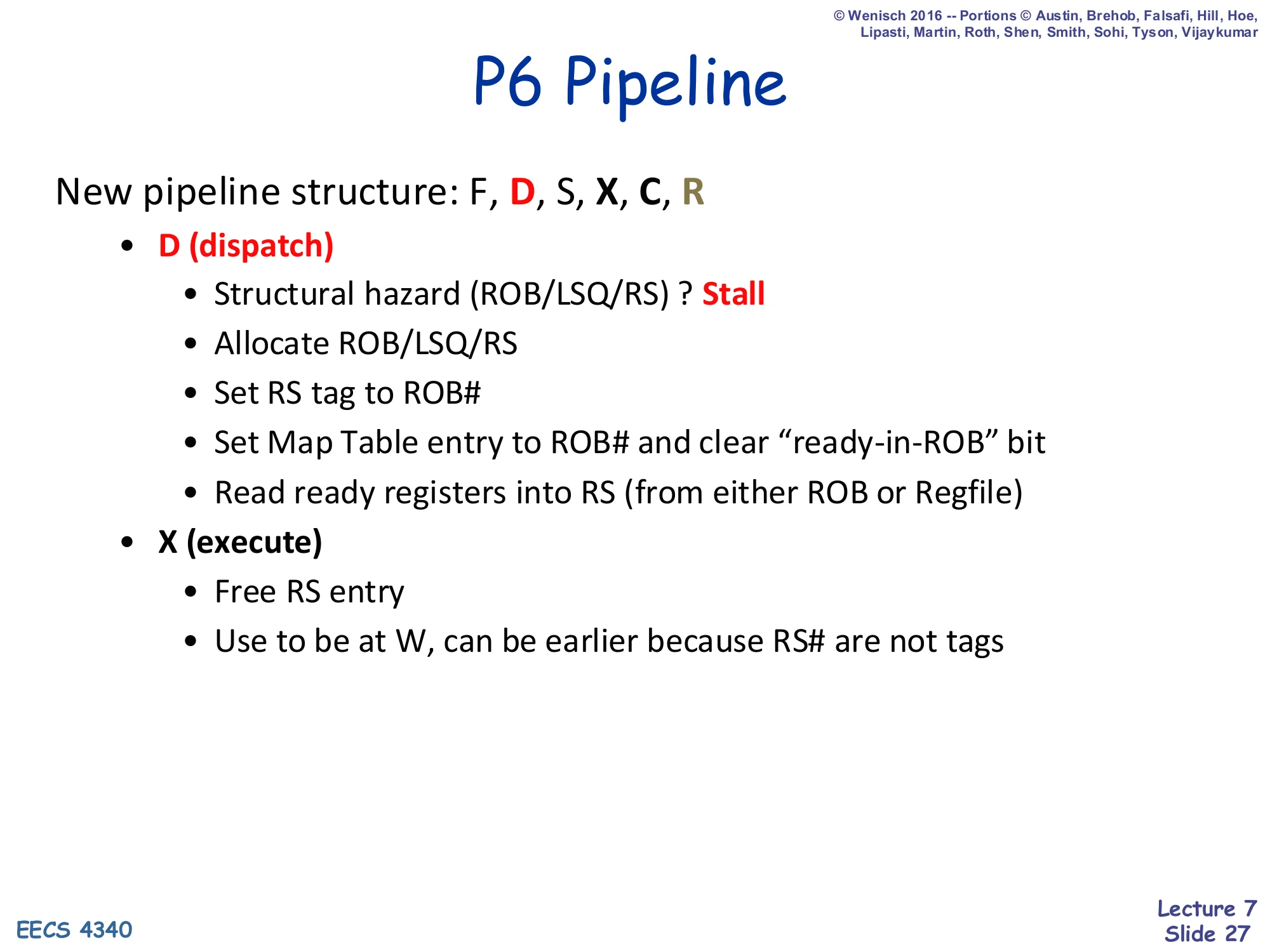
New pipeline structure: F, D, S, X, C, R
- D (dispatch)
- Structural hazard (ROB/LSQ/RS) ? Stall
- Allocate ROB/LSQ/RS
- Set RS tag to ROB#
- Set Map Table entry to ROB# and clear “ready-in-ROB” bit
- Read ready registers into RS (from either ROB or Regfile)
- X (execute)
- Free RS entry
- Use to be at W, can be earlier because RS# are not tags
The P6 pipeline grows from F/D/S/X/W to F/D/S/X/C/R: writeback splits into Complete and Retire. Dispatch acquires more responsibilities than in plain Tomasulo — it now allocates three structures (ROB slot, RS slot, and an LSQ slot if it’s a memory op) and any of them being full causes a stall. The dispatched instruction’s RS tag is the ROB#, not a free RS index. The dispatcher updates the Map Table entry for the destination register to the new ROB# and clears the + bit (no value yet). It reads sources from regfile or ROB depending on whether the source’s T+ is 0, T, or T+. Importantly, an RS slot can be freed at X rather than waiting until W — because the RS index is no longer the tag (the ROB# is), there are no in-flight references to the RS to keep alive after execute begins.
P6 Pipeline (C and R stages)
Show slide text
P6 Pipeline (continued)
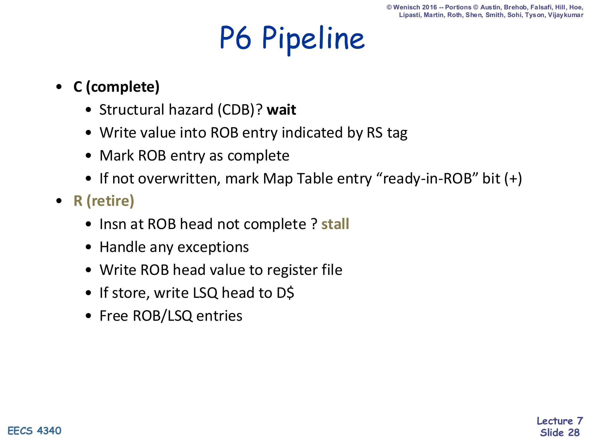
- C (complete)
- Structural hazard (CDB)? wait
- Write value into ROB entry indicated by RS tag
- Mark ROB entry as complete
- If not overwritten, mark Map Table entry “ready-in-ROB” bit (+)
- R (retire)
- Insn at ROB head not complete ? stall
- Handle any exceptions
- Write ROB head value to register file
- If store, write LSQ head to D$
- Free ROB/LSQ entries
Complete and retire mirror dispatch. Complete fights only for the CDB: if some other unit is broadcasting this cycle, this one waits. When it does broadcast, it writes the value into its ROB slot, marks the slot complete, and — if the Map Table still points at this ROB# — sets the + bit so that any subsequent dispatcher can read the value out of the ROB. Retire examines only the ROB head. If incomplete, the whole pipe stalls behind it. If complete, the hardware first checks for exceptions (this is the moment a precise handler is invoked), then writes the value to the regfile (and the store buffer head to the D-cache, if a store), then frees the ROB and LSQ slots.
P6 Dispatch (D): Part I
Show slide text
P6 Dispatch (D): Part I
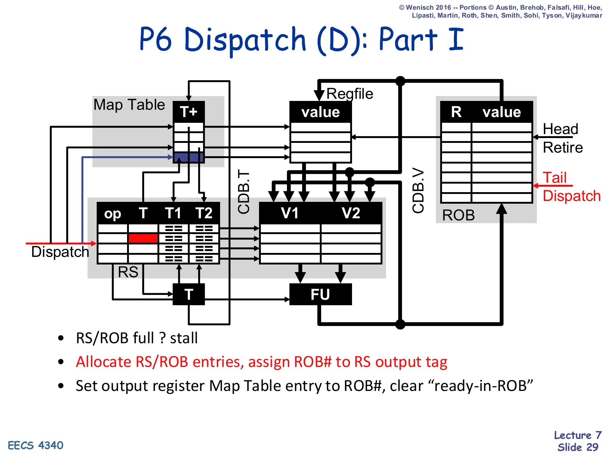
Diagram: red arrow from Dispatch input → Map Table entry (T+ written) → through to RS T column. Tail/Dispatch arrow on the ROB increments.
- RS/ROB full ? stall
- Allocate RS/ROB entries, assign ROB# to RS output tag
- Set output register Map Table entry to ROB#, clear “ready-in-ROB”
Step one of dispatch — allocation and renaming of the destination. Highlighted in the diagram: an RS row and a ROB row are reserved at the tail; the new ROB# is written into the RS’s T column (the output tag) and into the Map Table entry of the destination register, with the + bit cleared because no value exists yet. Any future instruction that reads the same architectural register will see this ROB# tag in the Map Table.
P6 Dispatch (D): Part II
Show slide text
P6 Dispatch (D): Part II
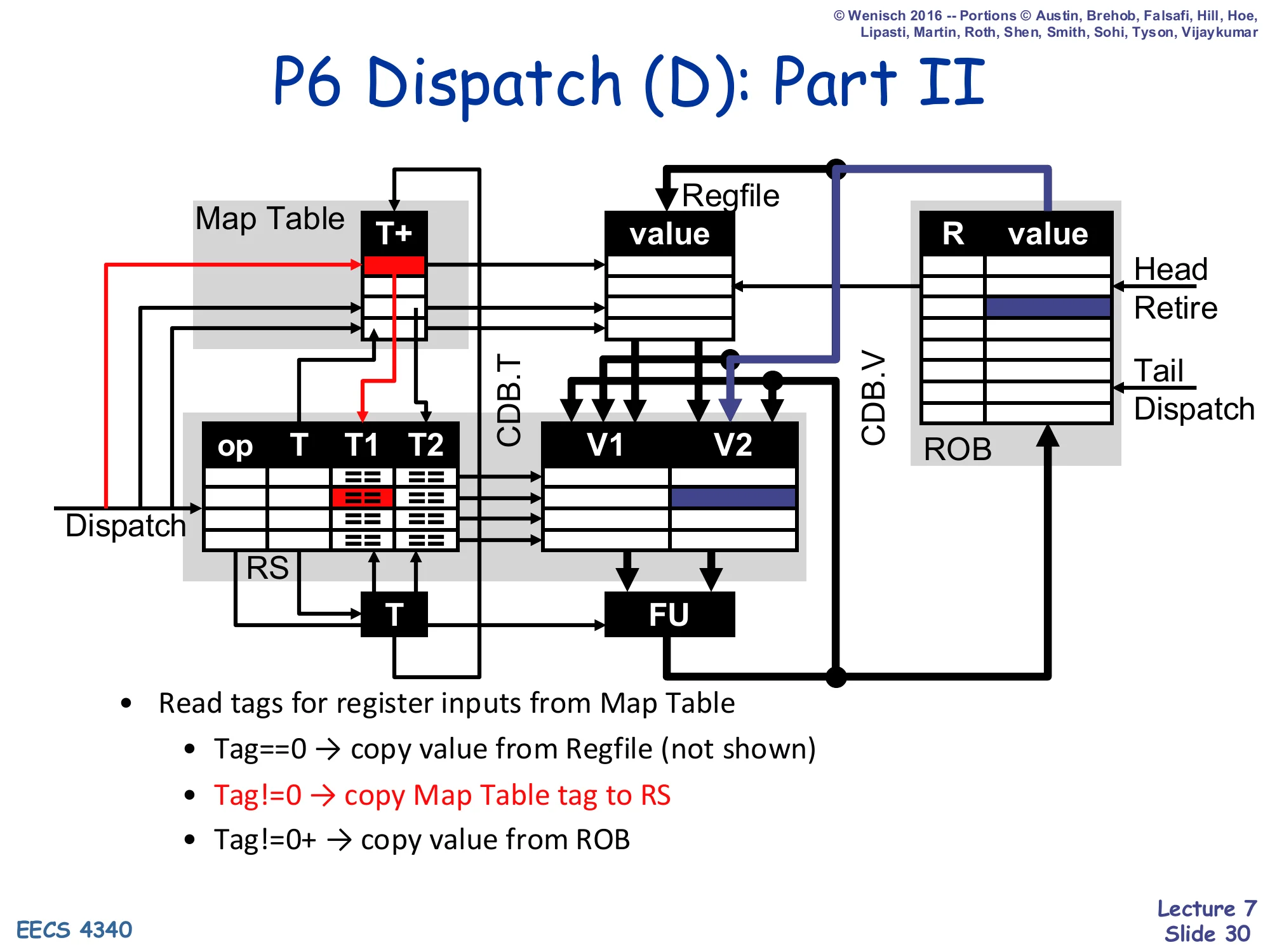
Diagram: red arrows show source-tag lookups from the Map Table to RS T1/T2; one arrow goes from the ROB value column back through to the RS V2 slot.
- Read tags for register inputs from Map Table
- Tag==0 → copy value from Regfile (not shown)
- Tag!=0 → copy Map Table tag to RS
- Tag!=0+ → copy value from ROB
Step two of dispatch — reading the sources. For each source register the dispatcher looks at the Map Table T+ entry. Three cases: T==0 means the regfile is the master (latch the value into V1/V2). T!=0 means an in-flight producer hasn’t completed yet (latch the tag into T1/T2 and wait for CDB broadcast). T!=0+ means an in-flight producer has completed but not yet retired — read the value out of ROB[T].V directly into V1/V2. This last case is the optimisation that the + bit enables: results live in the ROB for many cycles before retirement, and dependents do not need to wait.
P6 Complete (C)
Show slide text
P6 Complete (C)
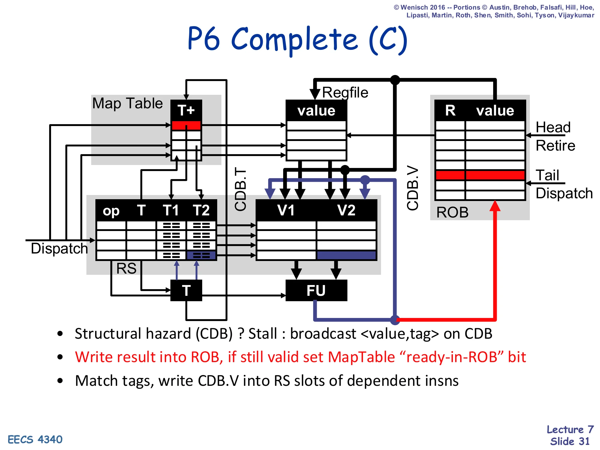
Diagram: an ALU output going onto CDB.V/CDB.T, then back into the ROB value column at the indicated row, into the RS V slots of dependent insns, and into the Map Table’s + bit.
- Structural hazard (CDB) ? Stall : broadcast
<value, tag>on CDB - Write result into ROB, if still valid set MapTable “ready-in-ROB” bit
- Match tags, write CDB.V into RS slots of dependent insns
Complete is the writeback half of plain Tomasulo plus an extra ROB write. If the CDB is occupied, wait. Otherwise broadcast <value, ROB#>. The broadcast does three things in parallel: it writes the value into the ROB row indexed by the ROB#, it tag-matches against every RS slot’s T1/T2 (filling V1/V2 for any waiter), and — if the Map Table still points at this ROB# — it sets the + bit. The qualifier if still valid matters: a younger instruction may have already redefined the architectural destination, so its ROB# is now in the Map Table; in that case this older completion still writes into its ROB slot but does not touch the Map Table.
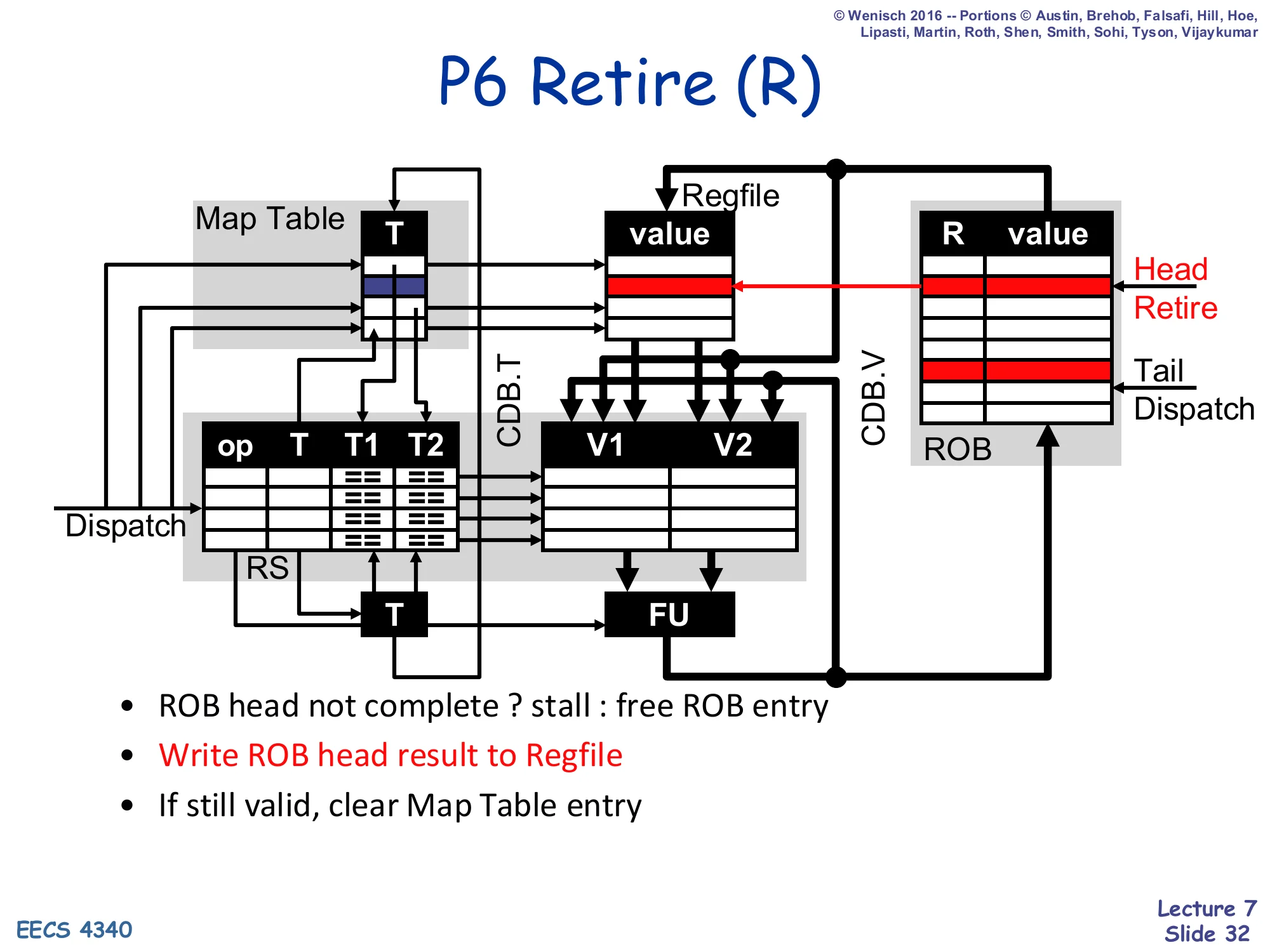
P6 Retire (R)
Show slide text
P6 Retire (R)
Diagram: ROB Head/Retire pointer increments; an arrow goes from the ROB row’s value into the regfile row; the Map Table entry for the retiring register is cleared (highlighted blue/red).
- ROB head not complete ? stall : free ROB entry
- Write ROB head result to Regfile
- If still valid, clear Map Table entry
Retire is the in-order half. The hardware looks only at the ROB head. If the head’s instruction has not yet completed (no value, no exception flag), it stalls. Otherwise it commits: the value is written to the regfile, the LSQ head is committed to the D-cache if this is a store, the ROB and LSQ slots are freed, and the Map Table entry is cleared only if the entry still points at this ROB# (a younger writer of the same register would have overwritten it). After retirement, by definition, the architectural state is exactly as if the retired instruction were the most recent sequential instruction — i.e., the precise state invariant holds.
P6 Data Structures (recap)
Show slide text
P6 Data Structures
The full annotated diagram from slide 25, repeated as a reference card before the worked example.
- Insn fields and status bits
- Tags
- Values
Reference reminder of the P6 microarchitecture’s full state — Map Table with T+, reservation stations with op/T/T1/T2 and V1/V2, regfile, ROB with R/value, and the CDB tying them all together. The next many slides walk this state cycle-by-cycle through the seven-instruction example.
P6 Data Structures (initial state for example)

Show slide text
P6 Data Structures
Same ROB / Map Table / RS template as slide 26: the seven-instruction trace ldf / mulf / stf / addi / ldf / mulf / stf is loaded but not yet dispatched. Map Table all zero. All RSes idle.
Initial state right before cycle 1 of the worked example: the ROB has the program order written in but no head/tail pointers set yet, the Map Table is all zero (everything in the regfile is the master), and all five reservation stations are idle. The next twelve slides walk forward one cycle at a time.
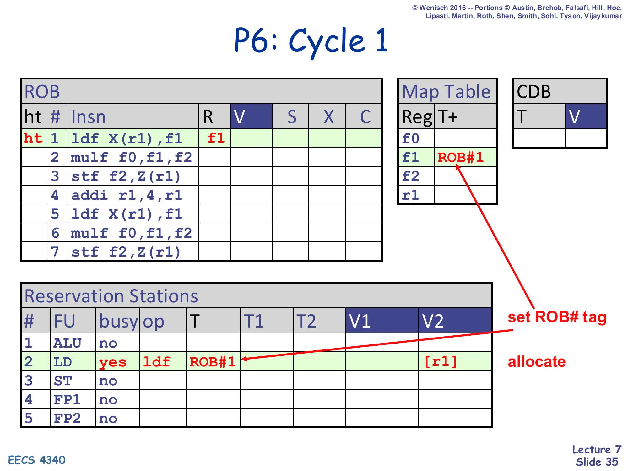
P6: Cycle 1
Show slide text
P6: Cycle 1
- ROB head and tail point at row 1 (
ldf X(r1),f1); R=f1 - Map Table: f1 ← ROB#1 (set ROB# tag)
- RS#2 (LD): busy=yes, op=ldf, T=ROB#1, V2=
[r1](allocate)
Cycle 1: dispatch the load. We allocate ROB row 1 and RS row 2 (the LD station), set RS#2’s output tag to ROB#1, and update Map Table f1 ← ROB#1. Source r1 is read from the regfile and stored as V2 = [r1]. The Map Table for r1 is still zero, so no tag is needed.
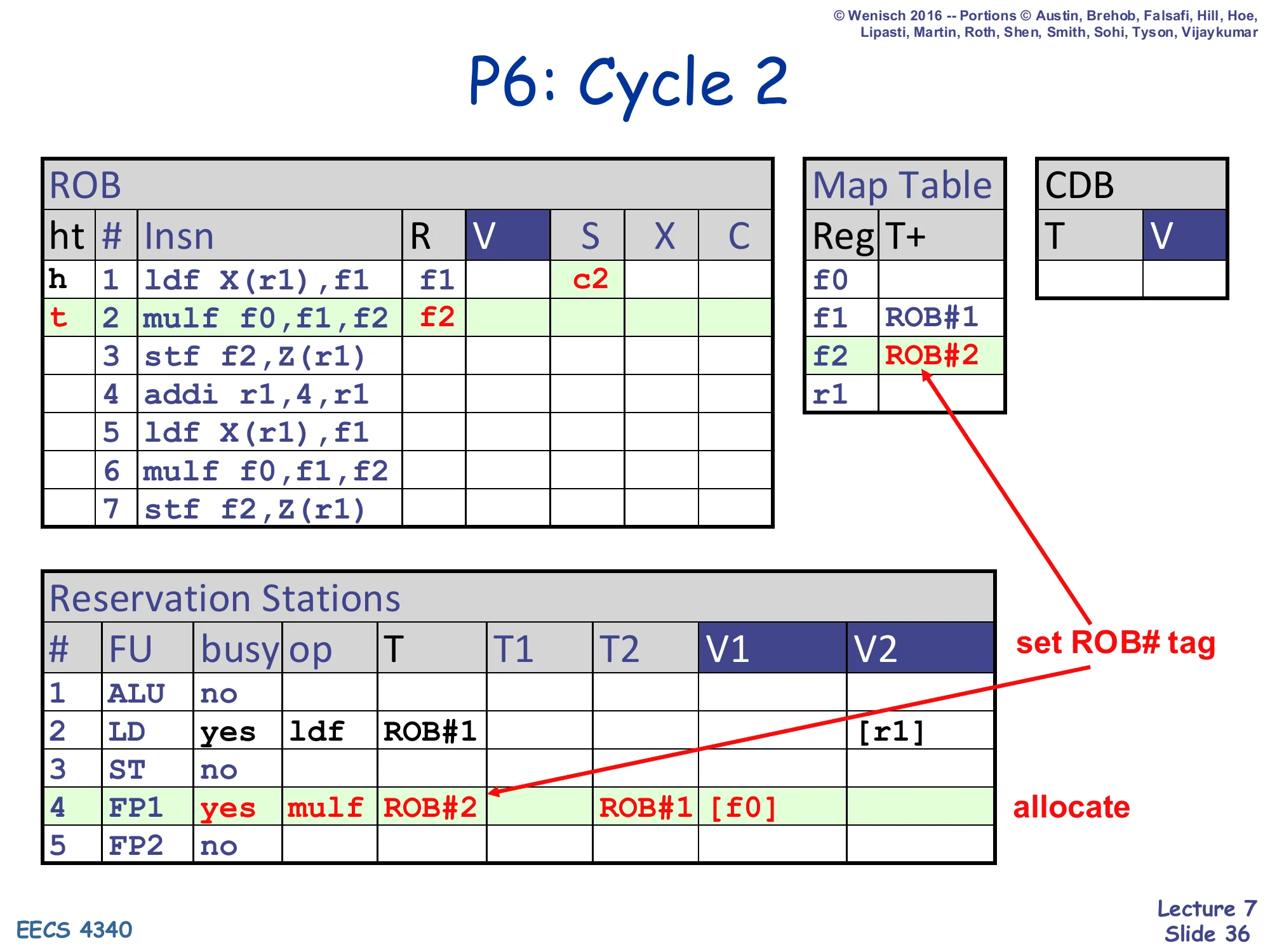
P6: Cycle 2
Show slide text
P6: Cycle 2
- ROB row 1: ldf, R=f1, S=c2; row 2: mulf, R=f2 (tail moves to row 2)
- Map Table: f1 ← ROB#1, f2 ← ROB#2
- RS#2 still busy with ldf, ROB#1 (executing)
- RS#4 (FP1) allocated: busy=yes, op=mulf, T=ROB#2, T1=ROB#1 (waiting on f1), V1=
[f0](f0 ready in regfile)
Cycle 2: the load issues (S=c2); the multiply dispatches into FP1. The multiply needs f0 (regfile-ready, V1=[f0]) and f1 (in-flight, T1=ROB#1). Map Table f2 ← ROB#2. Note how the multiply finds ROB#1 in the Map Table for f1 and copies the tag into T1 — it does not stall, it waits.
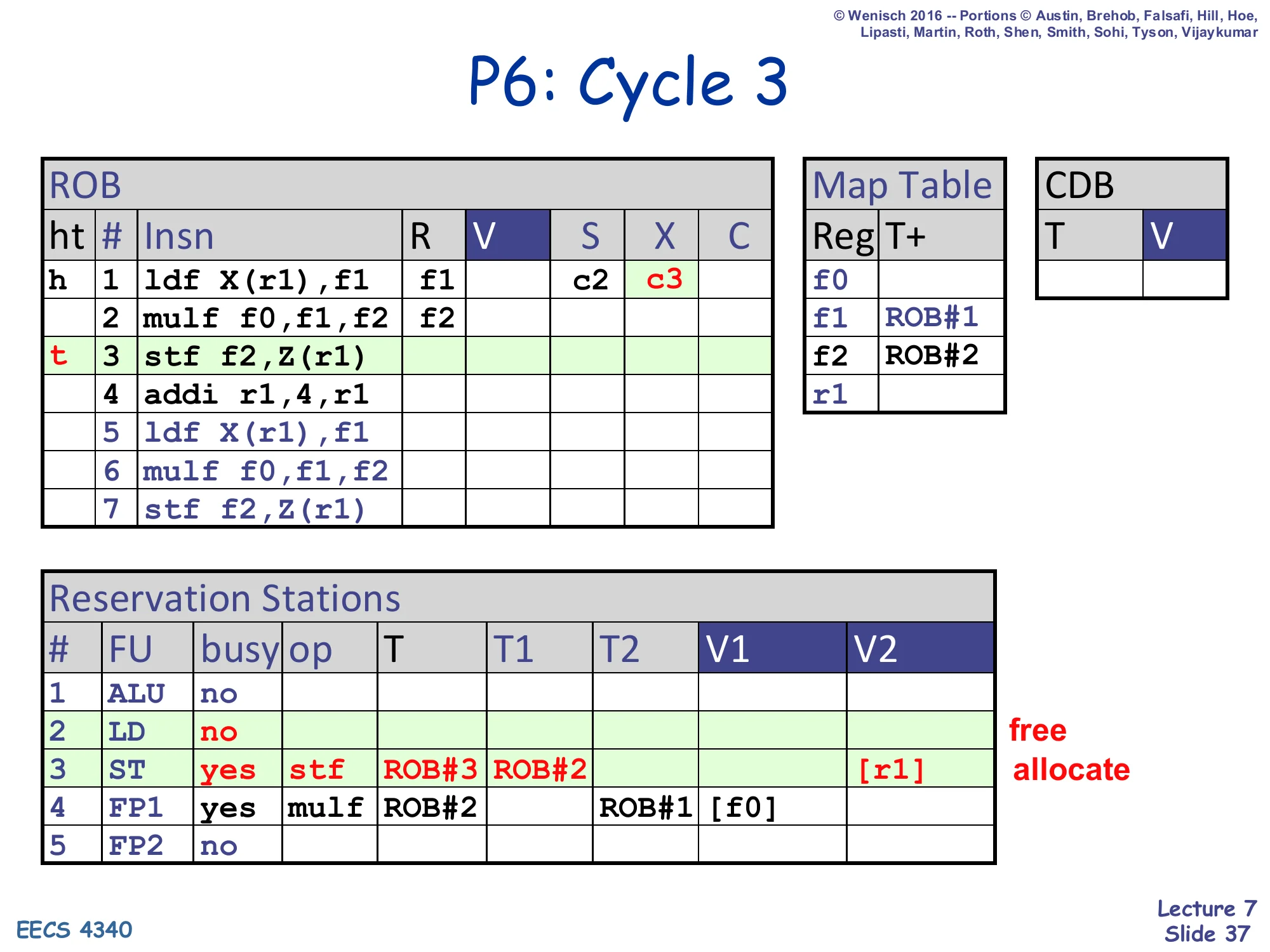
P6: Cycle 3
Show slide text
P6: Cycle 3
- ROB row 1: ldf, X=c3 (executing); row 3: stf f2,Z(r1) at tail
- Map Table unchanged for f1, f2; r1 still 0
- RS#2 (LD): freed (no, busy=no — early free at X)
- RS#3 (ST): busy=yes, op=stf, T=ROB#3, T1=ROB#3 (the store does not write a register so T self-references the ROB), T2=ROB#2, V2=
[r1](allocate)
Cycle 3: the load reaches X (X=c3). The LD reservation station is freed early — at X, not at writeback — because RS# is no longer the tag. The store dispatches into ST: it depends on f2 (ROB#2) and uses r1 directly from the regfile. T1=ROB#3 is the store’s own ROB# slot since stores do not produce a register result; the slide annotates this ROB#3 ROB#2 to show the two source tags.
P6: Cycle 4
Show slide text
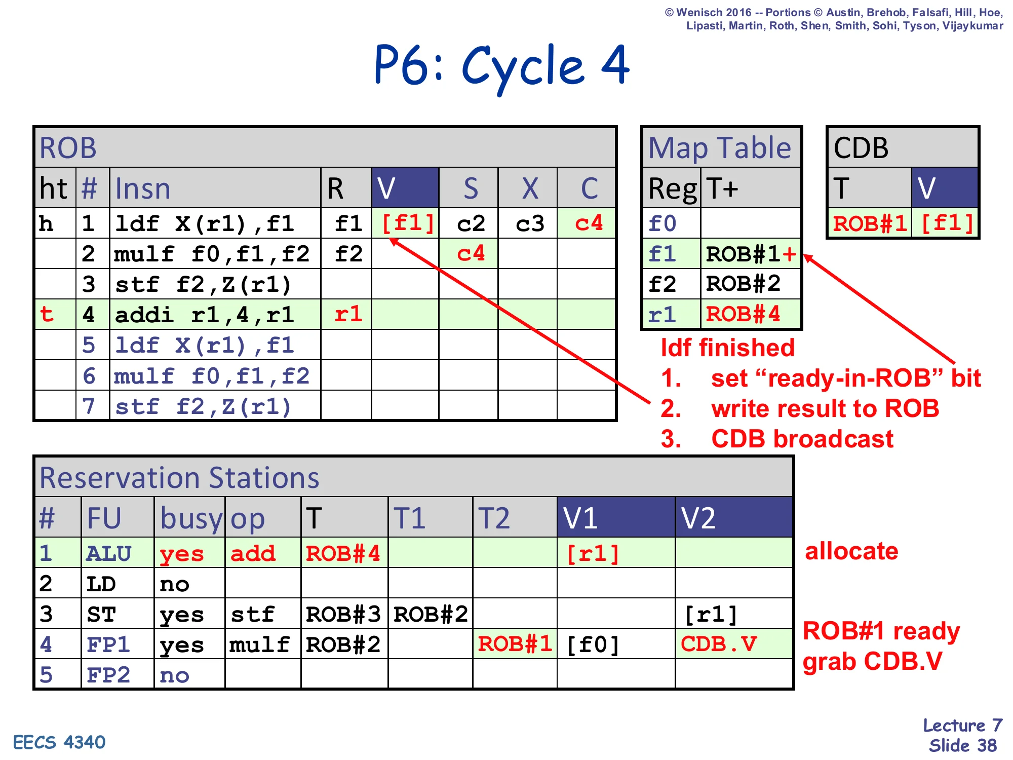
P6: Cycle 4
- ROB row 1: ldf finished — V=
[f1], C=c4 - Map Table f1 ← ROB#1+ (ready-in-ROB bit set)
- CDB: T=ROB#1, V=
[f1] - ROB row 4 (addi r1,4,r1) at tail; R=r1; Map Table r1 ← ROB#4
- RS#1 (ALU) allocated: busy=yes, op=add, T=ROB#4, V2=
[r1] - RS#4 (FP1): mulf, ROB#2, T1 cleared, V1=
[f0], V2 grabs CDB.V (ROB#1’s value)
ldf finished:
- set “ready-in-ROB” bit
- write result to ROB
- CDB broadcast
Cycle 4: the load’s value [f1] arrives. Three things happen in parallel: the value is written into ROB[1].V, the CDB broadcasts <ROB#1, [f1]>, and the Map Table f1 entry’s + bit is set (because Map Table[f1] still equals ROB#1, no younger writer has displaced it). Dependent RS slots (the multiply on FP1, T1=ROB#1) tag-match and grab the value into V1. The new dispatch this cycle is addi r1,4,r1 into ALU; ROB#4 is allocated and Map Table r1 ← ROB#4.
P6: Cycle 5
Show slide text
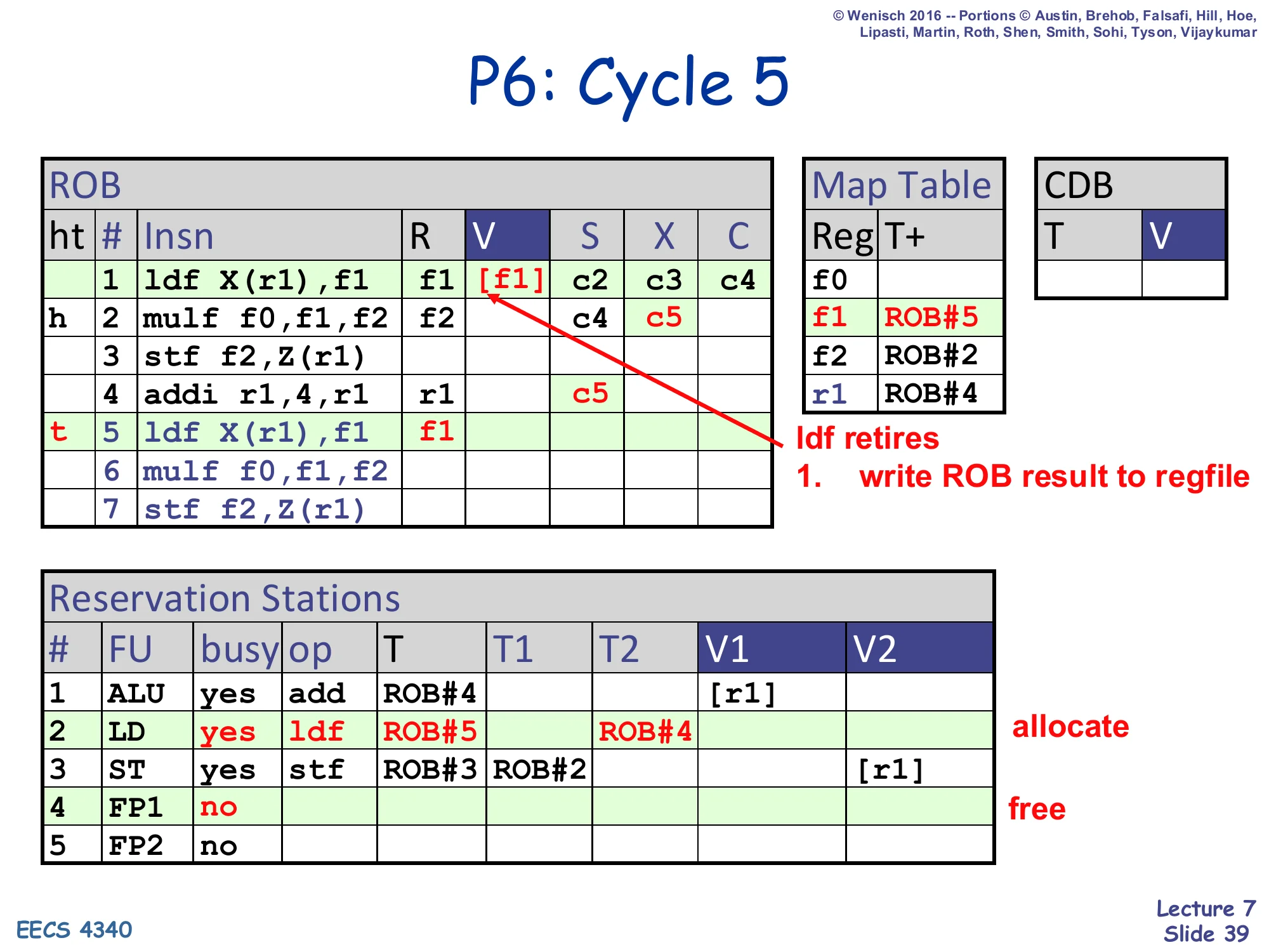
P6: Cycle 5
- ROB head moves: row 1 retires (ldf write
[f1]to regfile), row 2 (mulf) becomes head (h) - ROB row 4 addi: X=c5 (executing on ALU)
- ROB row 5 ldf X(r1),f1 at tail; R=f1; Map Table f1 ← ROB#5
- ROB row 2 mulf: S=c4, X=c5 (issued, executing)
- RS#2 (LD): allocated for the second ldf — busy=yes, op=ldf, T=ROB#5, T2=ROB#4 (waiting on r1)
- RS#4 (FP1): freed (mulf moved to X)
ldf retires:
- write ROB result to regfile
Cycle 5: the first ldf retires — its [f1] flows from ROB[1].V to the regfile, and the ROB head advances. Because Map Table[f1] now equals ROB#5 (just dispatched), the retire of ROB#1 does not clear the Map Table entry (it has been overwritten by a newer producer). The mulf executes in FP1 (X=c5); ALU starts addi (X=c5). The second ldf dispatches and immediately depends on the in-flight addi — its T2=ROB#4.
P6: Cycle 6
Show slide text
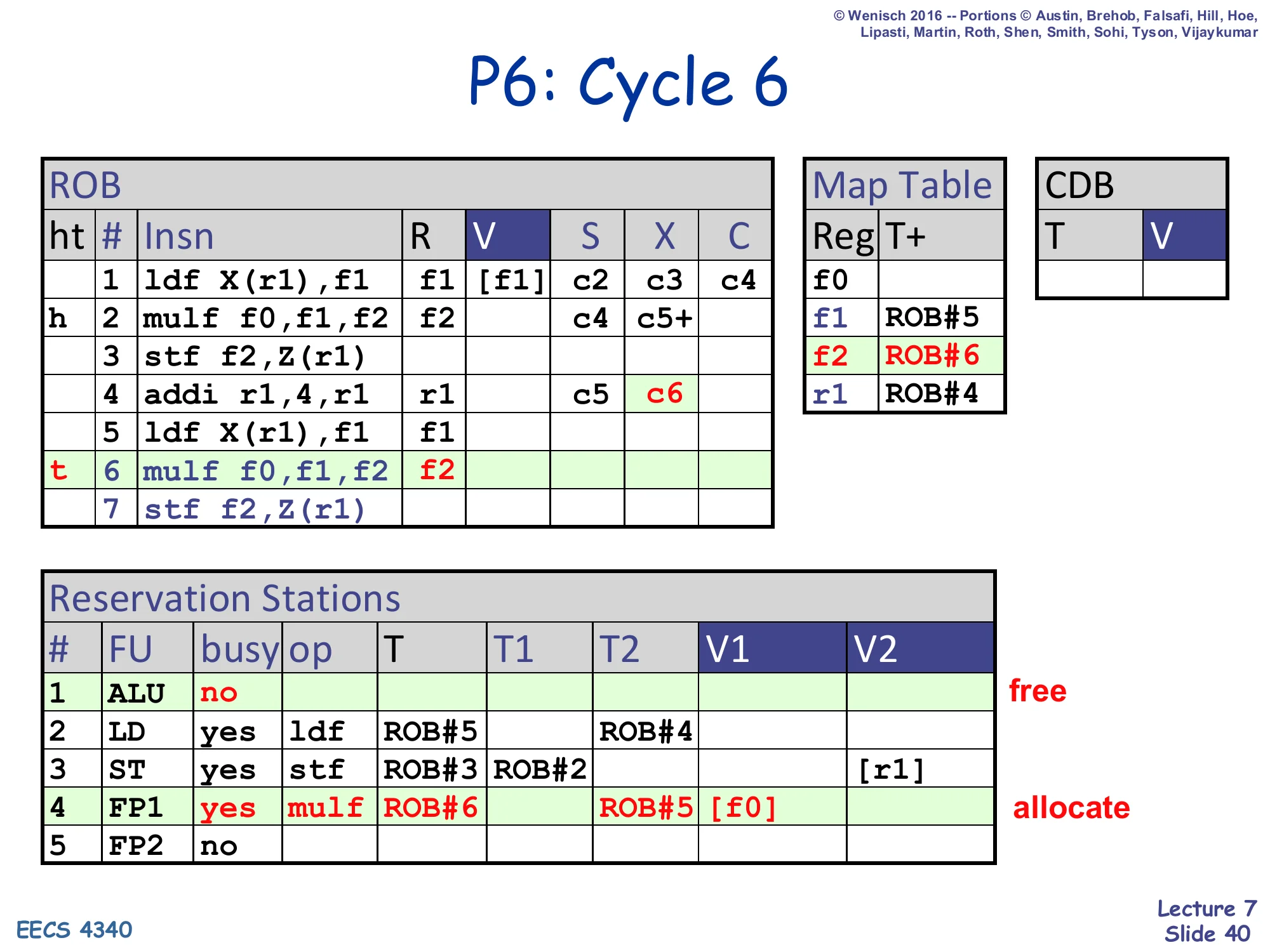
P6: Cycle 6
- ROB row 4 addi: X=c6
- ROB row 6 mulf f0,f1,f2 at tail; R=f2; Map Table f2 ← ROB#6
- RS#1 (ALU): freed
- RS#4 (FP1): allocate again — busy=yes, op=mulf, T=ROB#6, T1=ROB#5 (f1 still in-flight), V1=
[f0] - ROB row 2 mulf: still X (3-cycle FP, in cycles c4..c6); slide marks c5+ in column X meaning “finishing in c6”
Cycle 6: the second mulf dispatches. Its f1 source maps to ROB#5 (still in-flight, second ldf), so T1=ROB#5. f0 is regfile-ready, V1=[f0]. Map Table f2 ← ROB#6. The first mulf is in its third execute cycle (3-cycle FP), denoted c5+.
P6: Cycle 7
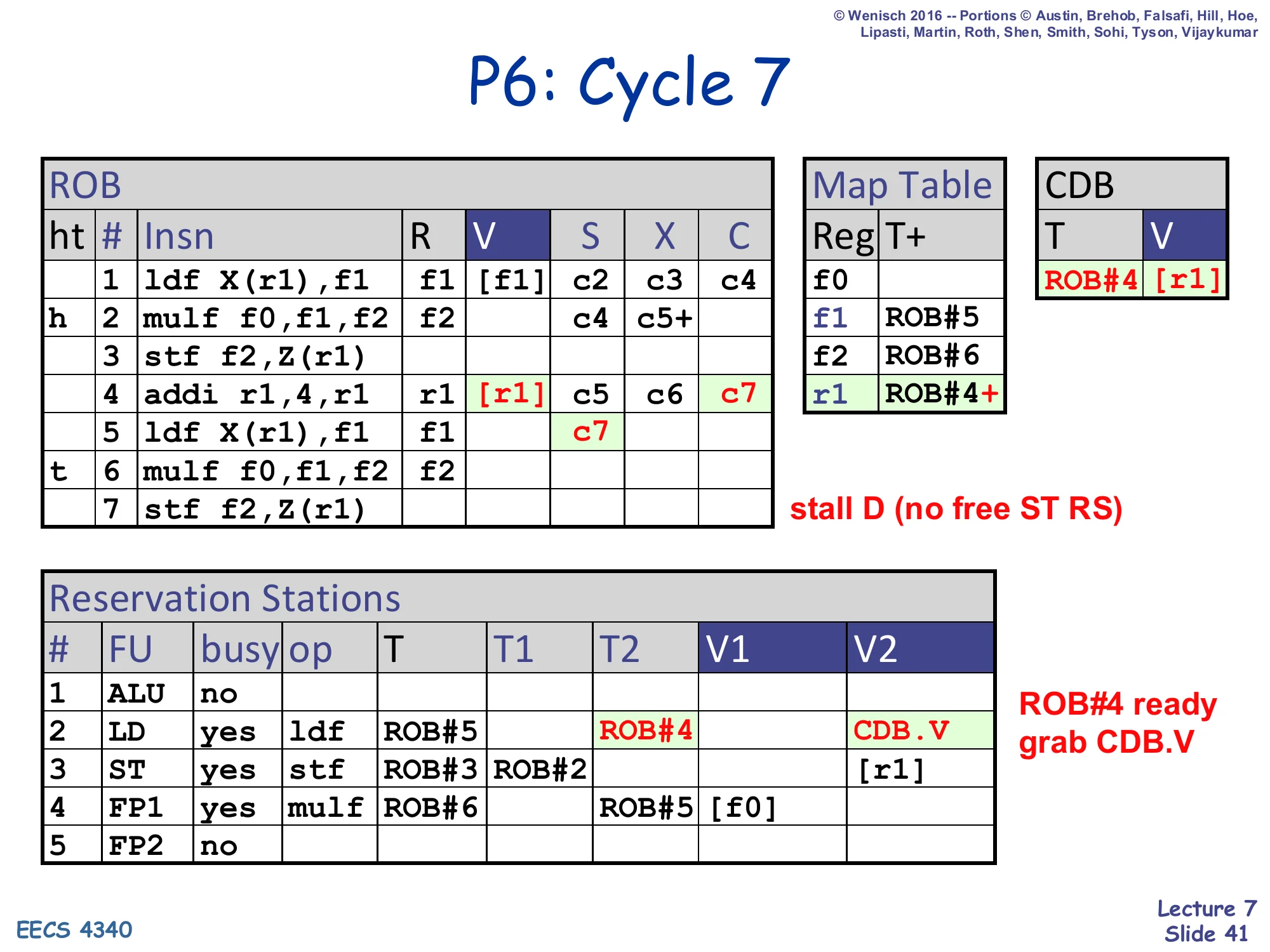
Show slide text
P6: Cycle 7
- CDB: T=ROB#4, V=
[r1]— addi completes - ROB row 4 addi: V=
[r1], C=c7 - Map Table r1 ← ROB#4+ (ready-in-ROB)
- ROB row 5 ldf: S=c7 (issues now that r1 is ready)
- Stall D (no free ST RS) — instruction 7 (
stf) cannot dispatch - RS#2 (LD): T2 picks up CDB.V — ldf grabs r1 value
Cycle 7: addi completes; ROB#4.V = [r1], Map Table r1 ← ROB#4+. The second ldf issues (S=c7), grabbing the broadcast [r1] into its RS V2. Dispatch stalls because the ST reservation station is still busy with the first store — the front-end has structurally backed up, but the back-end keeps making progress. This illustrates how a structural hazard in P6 only blocks dispatch, not execution.
P6: Cycle 8
Show slide text
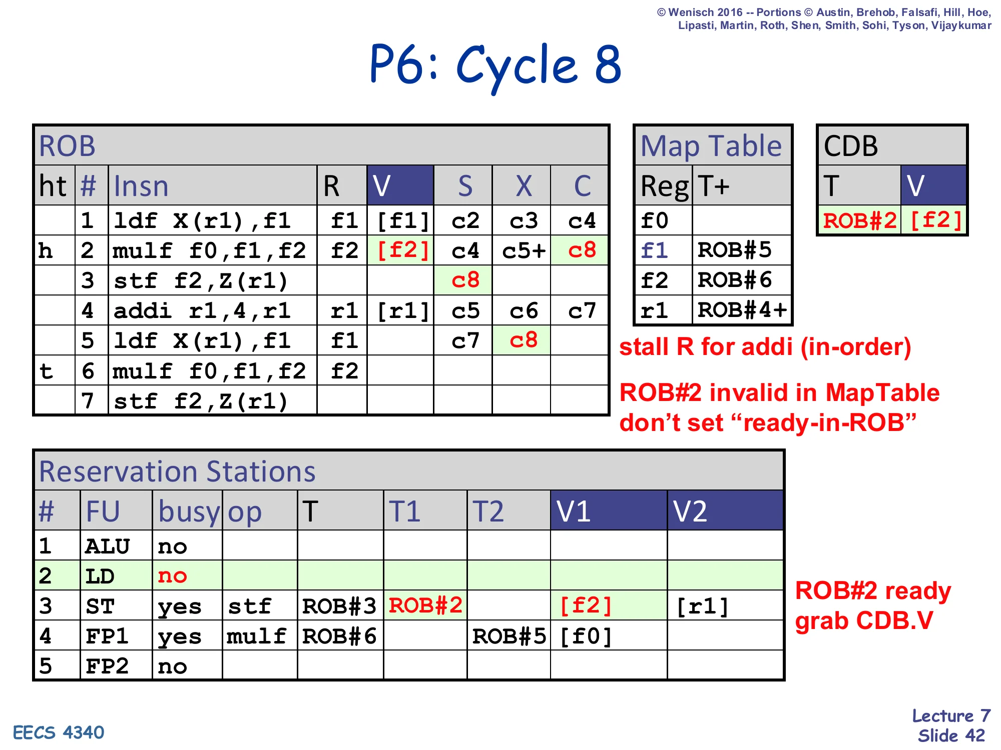
P6: Cycle 8
- CDB: T=ROB#2, V=
[f2]— mulf completes - ROB row 2 mulf: V=
[f2], C=c8 - ROB row 3 stf: S=c8
- ROB row 5 ldf: X=c8
- ROB#2 invalid in MapTable (Map Table[f2] is ROB#6 now): don’t set “ready-in-ROB” — but DO write ROB[2].V
- Stall R for addi (in-order, ROB head is mulf at row 2, mulf just completed this cycle)
- RS#2 (LD): freed; RS#3 (ST): grabs CDB.V into V1=
[f2] - ROB#2 ready, store grab CDB.V
Cycle 8: the first mulf broadcasts <ROB#2, [f2]>. The ROB[2].V is filled but the Map Table f2 entry is not updated because Map Table[f2] now points at ROB#6 (the second mulf, dispatched in cycle 6). The store at ROB#3 grabs the broadcast value into V1. The first store’s S is set to c8 (issues). Retire stalls because the ROB head is still ROB#2 and although it just completed, the ldf at ROB#1 is the head this cycle (or ROB#2 in this slide’s framing — the slide annotates stall R for addi (in-order) meaning that the in-order retire has to wait for older ROBs first).
P6: Cycle 9
Show slide text
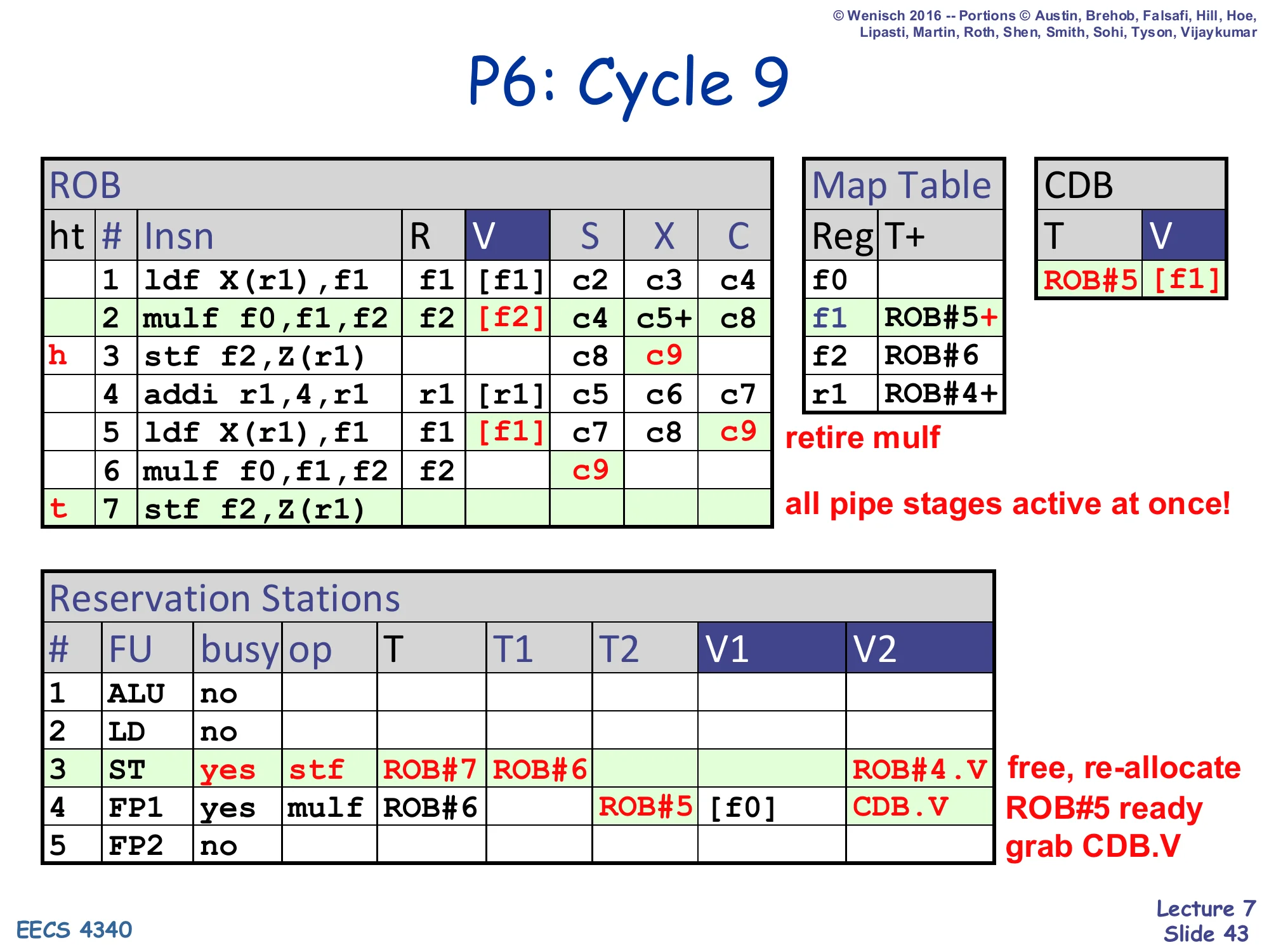
P6: Cycle 9
- CDB: T=ROB#5, V=
[f1]— second ldf completes - ROB row 2 mulf retires (h moves to row 3); regfile gets
[f2] - Map Table f1 ← ROB#5+ (still valid)
- ROB row 3 stf: X=c9 (executing)
- ROB row 5 ldf: V=
[f1], C=c9 - ROB row 6 mulf: S=c9 (issues, T1 grabs CDB.V into V1=
[f1]) - ROB row 7 stf finally dispatched at tail (ST RS#3 freed and re-allocated)
- RS#3 (ST): re-allocated — busy=yes, op=stf, T=ROB#7, T1=ROB#6 (waiting on f2 from second mulf)
- RS#4 (FP1) is busy with mulf ROB#6
retire mulf — all pipe stages active at once!
Cycle 9 is the steady-state cycle where every pipe stage is active simultaneously: dispatch (the second store), issue (mulf), execute (stf), complete (second ldf), and retire (first mulf). The second ldf broadcasts its value, which the second mulf grabs immediately. The first mulf retires, writing [f2] to the regfile; Map Table[f2] is not cleared because it now points at ROB#6, not ROB#2.
P6: Cycle 10
Show slide text
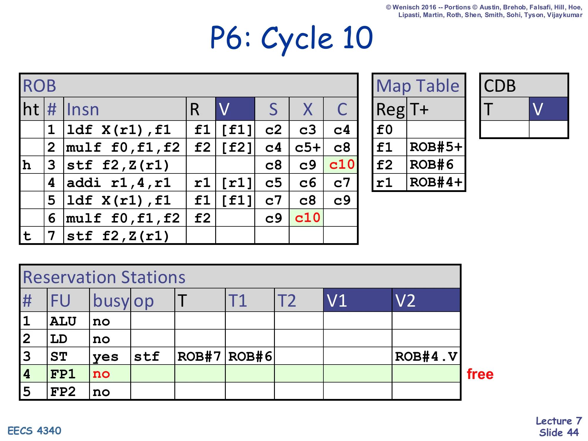
P6: Cycle 10
- ROB row 3 stf: C=c10 (head is now row 3)
- ROB row 5 ldf: V=
[f1], C=c9 (already) - ROB row 6 mulf: X=c10 (now executing on FP1, but slide shows c10 in the X column for row 6)
- RS#3 (ST): grabbed ROB#4.V — V2 column
- RS#4 (FP1): freed (mulf executed)
- ROB#5 ready+ in Map Table
Cycle 10: the first store completes (C=c10). The second mulf moves into X. The store reservation station (RS#3) holds ROB#4.V (the addi result for the second store’s address). FP1 is freed.
P6: Cycle 11
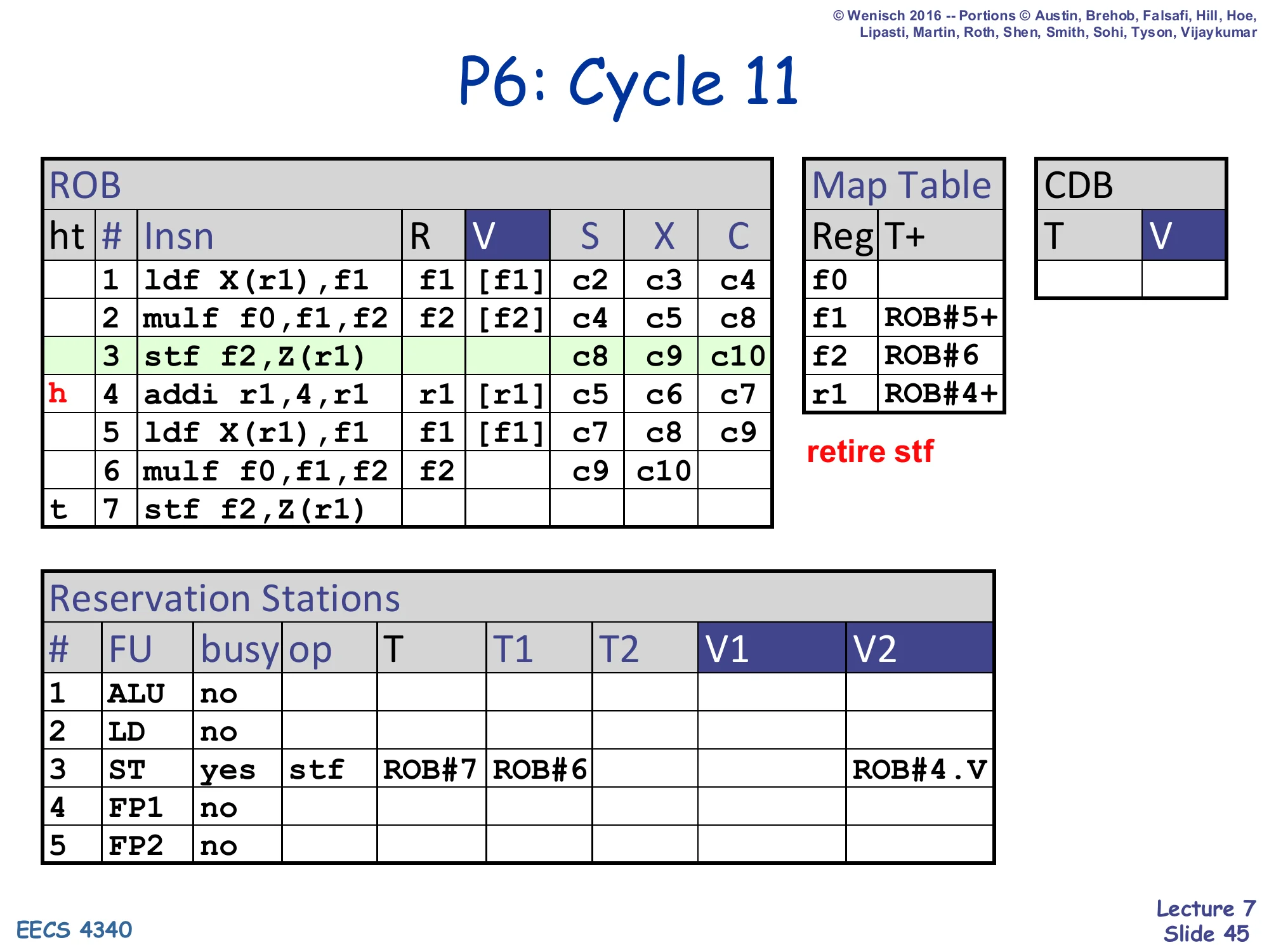
Show slide text
P6: Cycle 11
- ROB head moves: row 3 stf retires; row 4 addi at head
- All other ROB columns unchanged from cycle 10
- RS#3 (ST) still busy with second store
- retire stf
Cycle 11: the first store retires — meaning its value flows from the LSQ head into the D-cache. The ROB head advances to addi (ROB#4). Because the addi is already complete, it will retire next cycle.
Precise State in P6
Show slide text
Precise State in P6
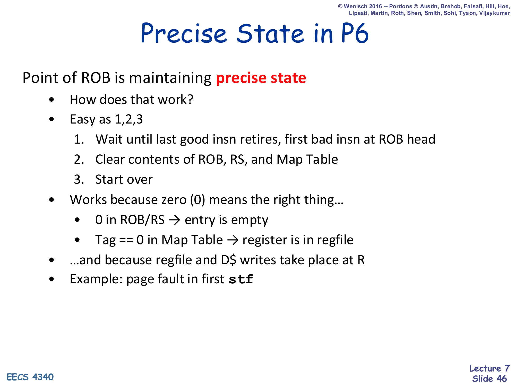
Point of ROB is maintaining precise state
- How does that work?
- Easy as 1,2,3
- Wait until last good insn retires, first bad insn at ROB head
- Clear contents of ROB, RS, and Map Table
- Start over
- Works because zero (0) means the right thing…
- 0 in ROB/RS → entry is empty
- Tag == 0 in Map Table → register is in regfile
- …and because regfile and D$ writes take place at R
- Example: page fault in first stf
The slide explains the mechanism behind precise state in three lines: (1) drain the ROB until the last instruction before the offender has retired and the offender is at the head; (2) zero the ROB, RS, and Map Table; (3) restart. The cleanup is trivial because the all-zeros state already means the right thing — empty ROB/RS slots and ‘value in regfile’ Map Table entries. And it is correct because the regfile and D-cache only ever change at retire (R), so anything that was speculatively executed but not retired never touched architectural state. The next slides walk through this for the concrete page-fault case.
P6: Cycle 9 (with precise state)
Show slide text
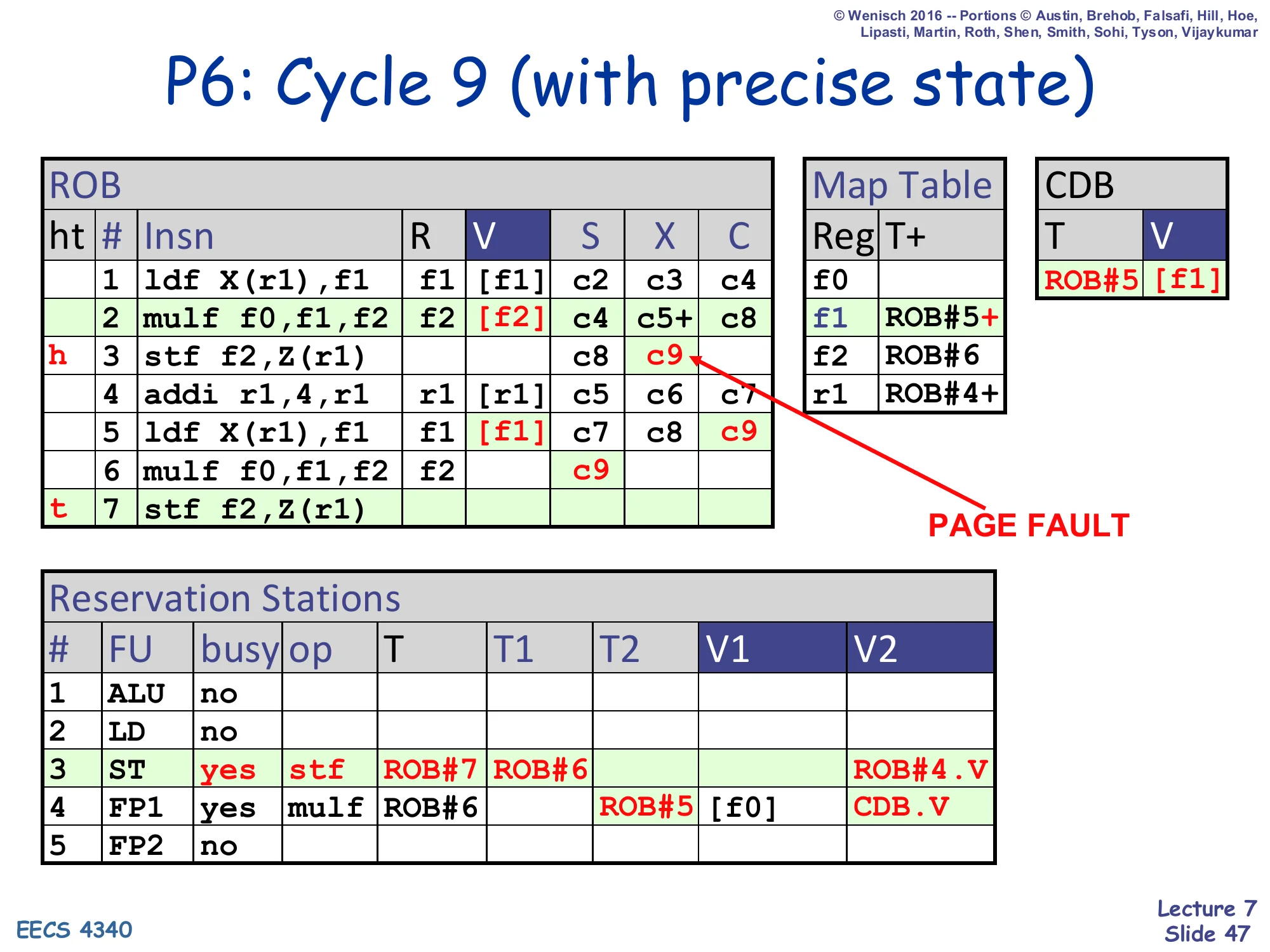
P6: Cycle 9 (with precise state)
Same state as cycle 9 but with PAGE FAULT marked on the first stf as it executes (X=c9). ROB row 3 stf reaches X with a fault flag.
ROB head still at row 2 (about to retire mulf, which is fine).
Retire stalls until row 2 commits, then row 3 (the faulting stf) becomes head.
Modified cycle 9: the first stf f2,Z(r1) raises a page fault during X. Crucially, the fault does not roll back anything yet — the store carries a fault flag in its ROB slot and otherwise behaves like a normal completion. All younger instructions (ldf at ROB#5, mulf at ROB#6) keep executing speculatively. The hardware does not need a separate fault-routing path; the ROB itself sequences the fault behind any older instruction.
P6: Cycle 10 (with precise state)
Show slide text
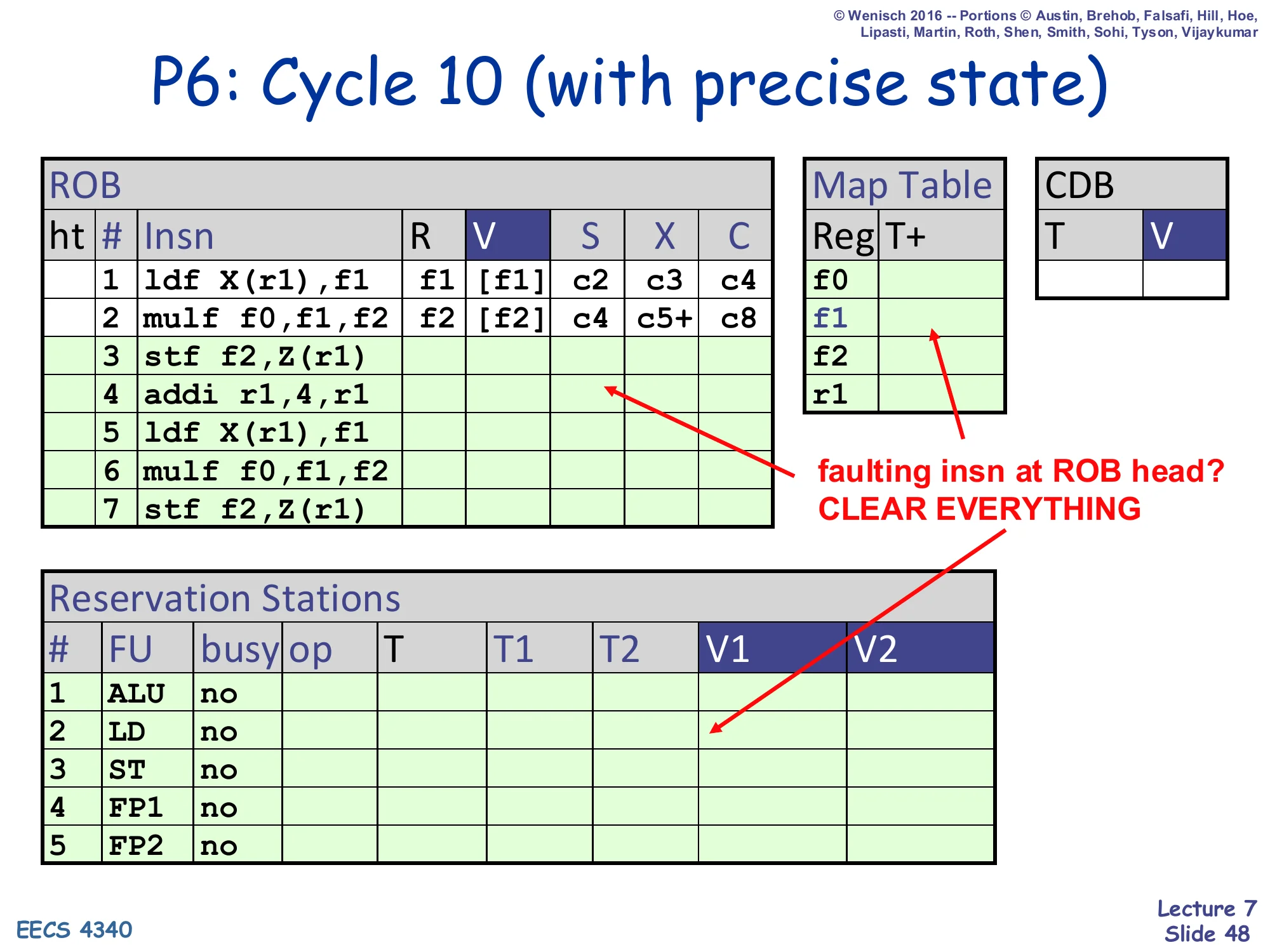
P6: Cycle 10 (with precise state)
- ROB row 3 stf at head — page fault recognized
- All ROB/RS/Map Table rows highlighted green and cleared
- faulting insn at ROB head? CLEAR EVERYTHING
Cycle 10 with precise state: the faulting stf reaches the ROB head. The hardware recognises the fault flag, commits nothing for this instruction, and clears every ROB row, every RS row, and every Map Table entry in one cycle. Because the regfile and D-cache have only seen retired writes (the ldf at ROB#1 and the mulf at ROB#2), the architectural state is exactly as if execution had stopped just before the stf — i.e., precise.
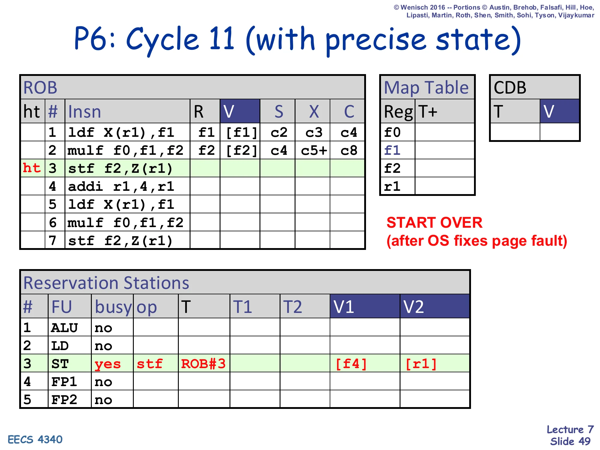
P6: Cycle 11 (with precise state)
Show slide text
P6: Cycle 11 (with precise state)
- ROB rows 1,2 retain their retired columns (V already written to regfile and D$)
- ROB rows 3..7 cleared — head and tail now both point at row 3 (the stf)
- RS#3 (ST): allocated again with stf, T=ROB#3, V1=
[f4], V2=[r1](fresh dispatch after OS fixes page fault) - START OVER (after OS fixes page fault)
Cycle 11 with precise state: the OS handler has run, mapped in the missing page, and resumed user code. Execution restarts from the faulting stf (ROB#3 again). The ROB has been replayed: head=tail=row 3, so the stf is dispatched anew. Notice that f4 appears in V1 — the slide demonstrates that the architectural register file already has the correct (retired) value of f2, but the example uses f4 to underscore that after restart the source operands come fresh from the regfile, untouched by any of the squashed speculative work.
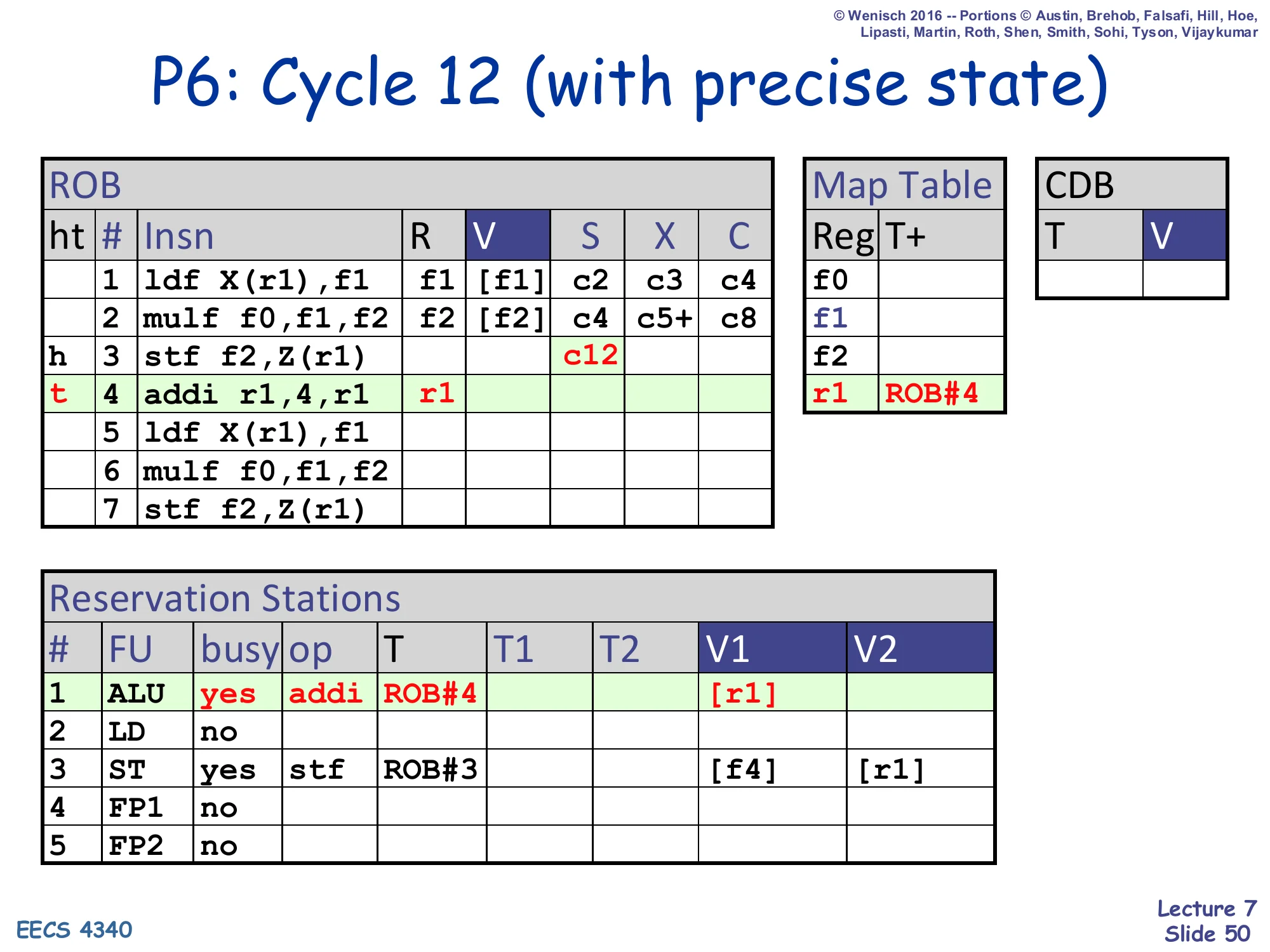
P6: Cycle 12 (with precise state)
Show slide text
P6: Cycle 12 (with precise state)
- ROB row 3 stf: S=c12 (issued)
- ROB row 4 addi at tail; r1 ← ROB#4 (Map Table)
- RS#1 (ALU): busy=yes, op=addi, T=ROB#4, V1=
[r1] - RS#3 (ST): still busy with stf
- The pipeline has fully resumed from the page fault.
Cycle 12 with precise state: the pipeline has caught up. The stf has issued, the addi has been re-dispatched into the ALU, and the ROB is rebuilding. From here onward execution looks identical to a normal in-order resumption from the faulting instruction — the user program cannot tell that anything happened. This is the entire payoff of the ROB-based design: a single mechanism, clear-and-restart, gives precise interrupts, speculative-misprediction recovery, and exception handling all at once.
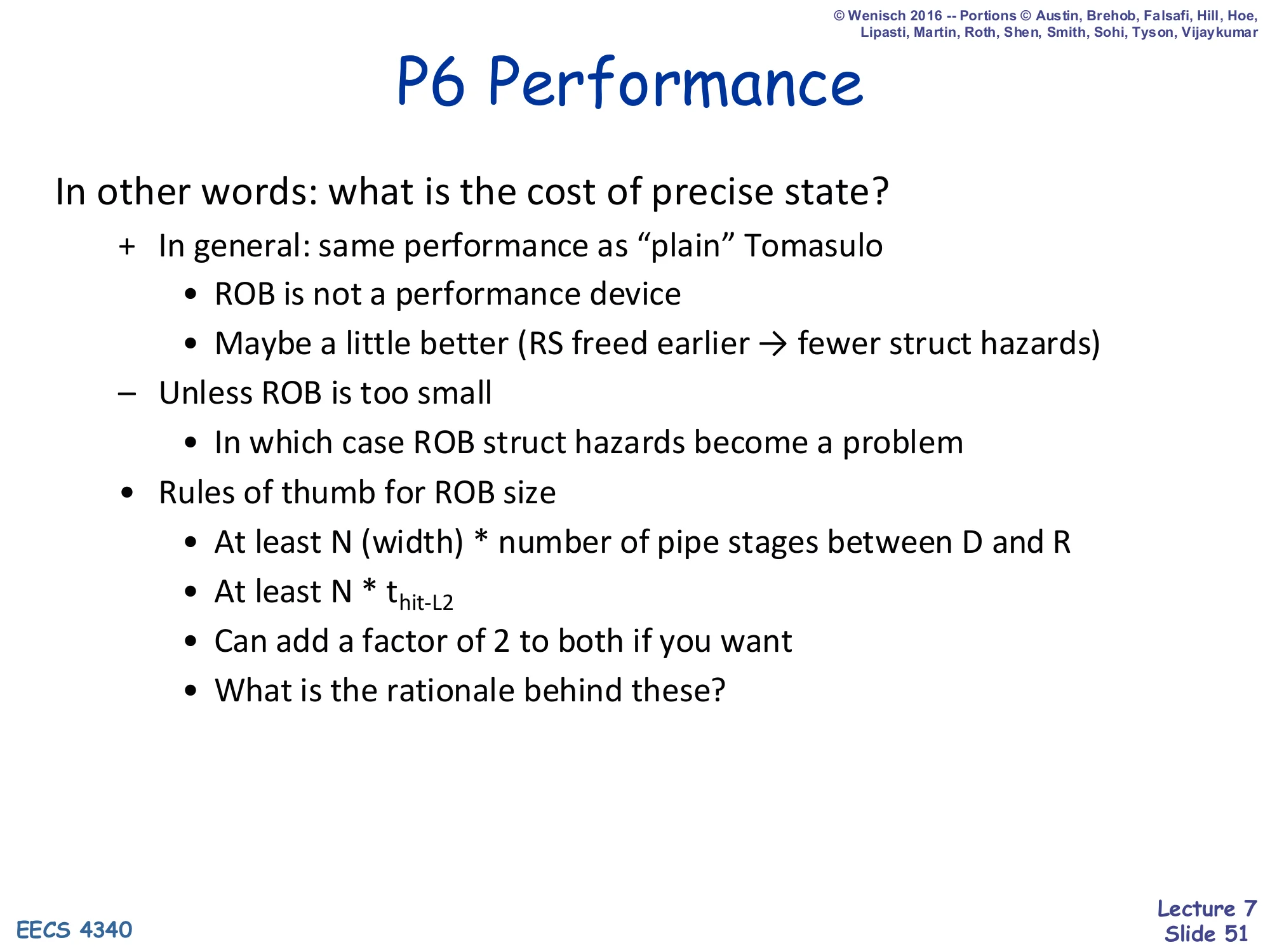
P6 Performance
Show slide text
P6 Performance
In other words: what is the cost of precise state?
-
- In general: same performance as “plain” Tomasulo
- ROB is not a performance device
- Maybe a little better (RS freed earlier → fewer struct hazards)
- − Unless ROB is too small
- In which case ROB struct hazards become a problem
- Rules of thumb for ROB size
- At least N (width) * number of pipe stages between D and R
- At least N * thit-L2
- Can add a factor of 2 to both if you want
- What is the rationale behind these?
Performance-wise, P6 essentially matches plain Tomasulo — the ROB is not a performance device, it is a correctness device for precise state. There is even a small win because reservation stations are now freed at X instead of W, reducing structural hazards on RS allocation. The only way the ROB hurts performance is if it is too small: dispatch then stalls on ROB-full. The rules of thumb size the ROB so that (a) the front-end can fully cover the dispatch-to-retire latency for issue width N, and (b) the ROB can hide an L2 hit latency, so a load miss doesn’t immediately back up the front-end.
P6 (Tomasulo+ROB) Redux
Show slide text
P6 (Tomasulo+ROB) Redux
Popular design for a while
- (Relatively) easy to implement correctly
- Anything goes wrong (mispredicted branch, fault, interrupt)?
- Just clear everything and start again
- Examples: Intel PentiumPro, IBM/Motorola PowerPC, AMD K6
Even made a comeback…
- Examples: Intel Pentium M
But went away for a while, why?
Reflective slide. The P6 design — Tomasulo + ROB — was the dominant high-performance design from the mid-1990s through ~2000 (Pentium Pro, Pentium II, Pentium III, AMD K6, several PowerPC chips), and then made a comeback in the Pentium M / Core / Core 2 family. Its appeal is conceptual simplicity: any time something goes wrong (misprediction, fault, async interrupt) the recovery action is the same — clear everything and restart. The teaser but went away for a while, why? is answered by the next slide: the value-movement bottleneck.
The Problem with P6
Show slide text
The Problem with P6
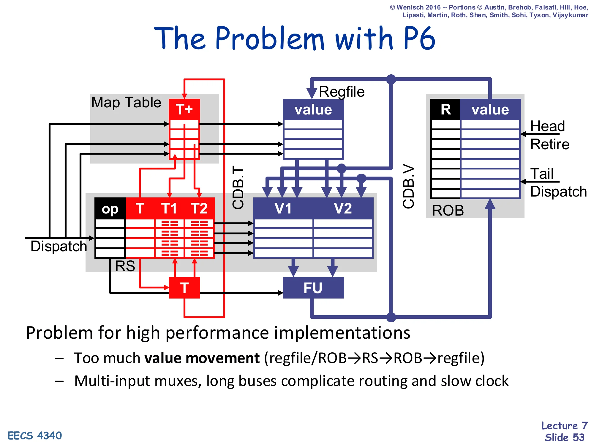
Full P6 data-structure diagram repeated.
Problem for high performance implementations
- Too much value movement (regfile/ROB→RS→ROB→regfile)
- Multi-input muxes, long buses complicate routing and slow clock
The flaw of value-based renaming for high-clock-rate designs: every value travels four times — from regfile or ROB into the RS at dispatch, from FU back into the ROB and onto the CDB at complete, and from ROB to regfile at retire. Each hop crosses long wires and multi-input muxes that lengthen the critical path. The fix, taken by the MIPS R10000 and later Intel cores, is physical-register-file renaming: keep one storage location per dynamic value (the physical register), and pass pointers instead of values. That is the topic of next week’s lecture — but it is precisely the lesson that makes P6 a good teaching design and a less competitive production design at multi-GHz clocks.
Readings (closing)
Show slide text
Readings
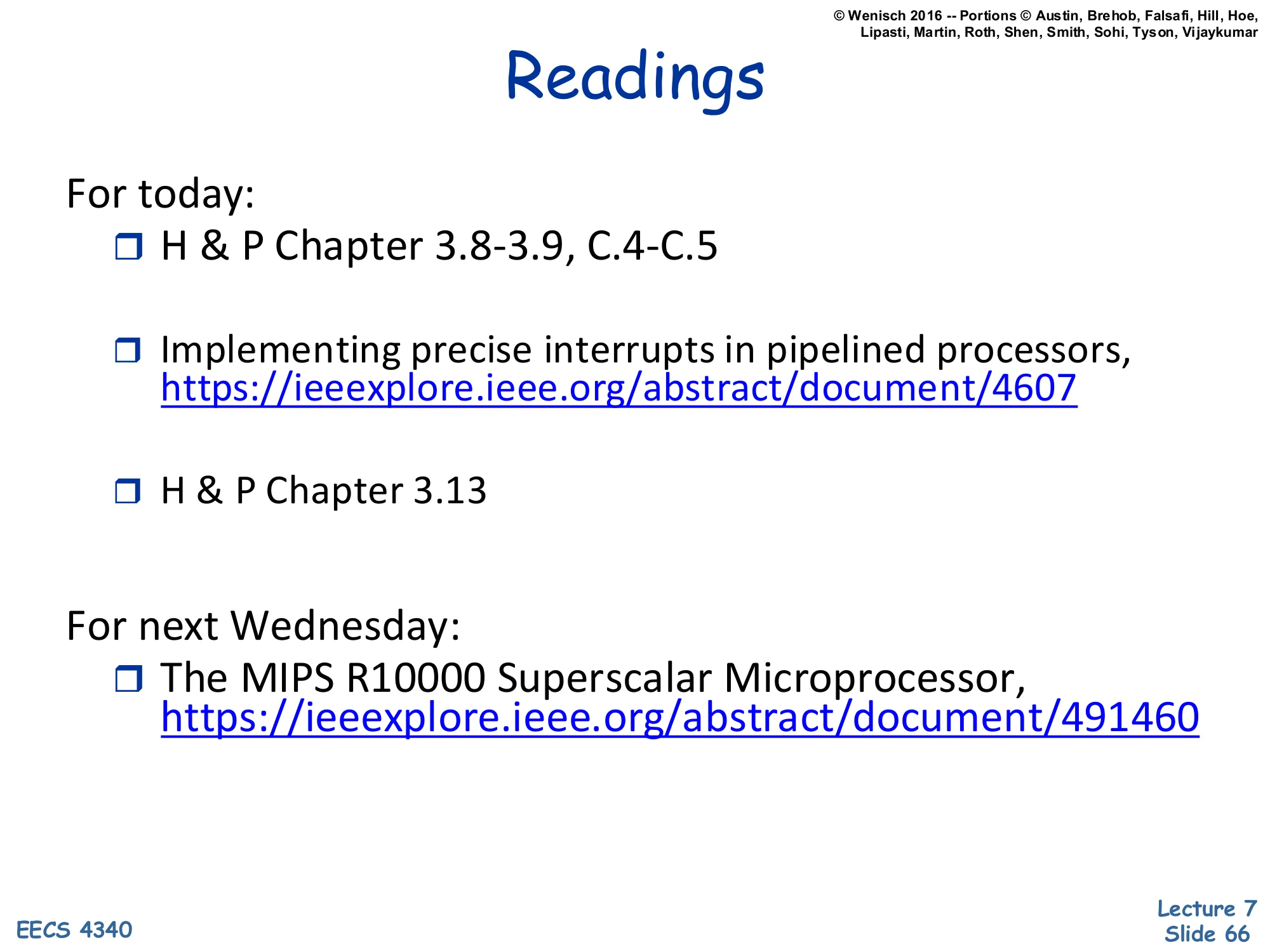
For today:
- H & P Chapter 3.8–3.9, C.4–C.5
- Implementing precise interrupts in pipelined processors, https://ieeexplore.ieee.org/abstract/document/4607
- H & P Chapter 3.13
For next Wednesday:
- The MIPS R10000 Superscalar Microprocessor, https://ieeexplore.ieee.org/abstract/document/491460
Closing reminder of today’s reading list and a forward pointer to next Wednesday’s case study (MIPS R10000), which introduces the physical-register-file alternative to P6’s value-based renaming. Same content as slide 3.
Announcements (closing)

Show slide text
Announcements
- Project #4
- Due: proposal, 4-Mar-26
- Mid-term exam
- 9-Mar-26
Closing logistics slide, identical to slide 2: Project #4 proposal due 4-Mar-26 and the mid-term on 9-Mar-26.